
2026-08-15
Understanding CNC Machining Tolerance Standards

CNC machining tolerance standards define the permissible dimensional variation on a finished part. ISO 2768 is the primary international standard, covering linear, angular, and geometric tolerances across four classes, fine (f), medium (m), coarse (c), and very coarse (v). Typical CNC tolerances range from ±0.005 mm for precision work to ±0.1 mm for standard parts. Tighter tolerances increase cost and lead time, so matching the tolerance class to the actual functional requirement is critical.
According to Protolabs’ engineering resources on CNC machining tolerances, understanding how tolerance specifications interact with material and process selection is one of the most impactful decisions a designer can make before submitting a part for production.
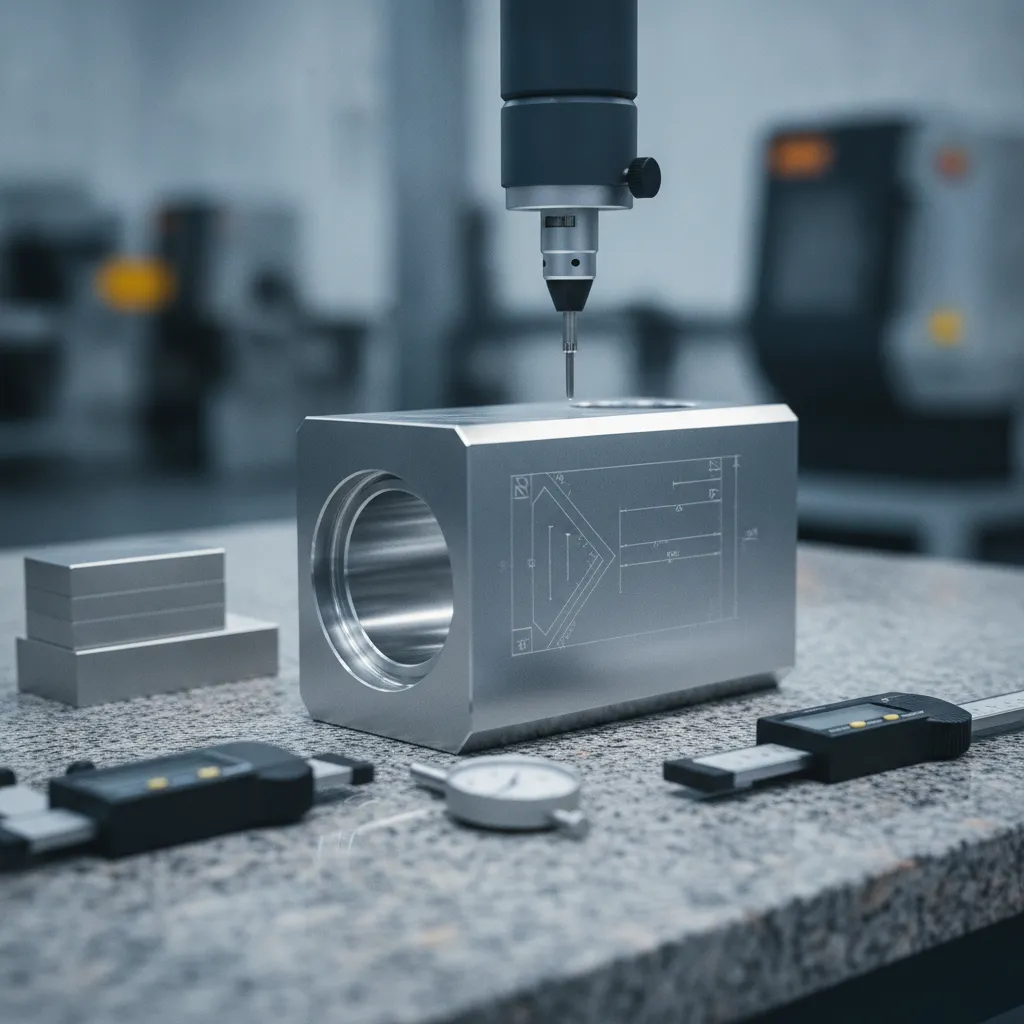
CNC Machining Tolerance Standards: ISO 2768 Classes Explained
ISO 2768 is the international framework that governs CNC machining tolerance standards, splitting into two parts that work together on any engineering drawing.
Part 1 covers linear and angular tolerances, the allowable deviation in lengths, diameters, and angles. Part 2 covers geometric tolerances, flatness, straightness, circularity, and similar form controls. A drawing that calls out “ISO 2768-m-K,” for example, applies medium linear tolerances from Part 1 and class K geometric tolerances from Part 2 simultaneously. Both parts must be read together to fully define a part’s permissible variation.
“Specifying the correct tolerance class from the outset is the single most effective way to control machining cost without compromising part function. Over-tolerancing is one of the most common and most avoidable sources of unnecessary expense in precision manufacturing.” — John Hanson, Senior Manufacturing Engineer, Protolabs
What Are the ISO 2768 Standard Classes (f, m, c, v) and When Should You Use Each?
ISO 2768 defines four tolerance classes, each matched to a specific manufacturing context:
- Fine (f): Used for precision instrument components and tight-fit assemblies. For a 30 mm nominal dimension, the allowable deviation is ±0.05 mm, appropriate for optical mounts, surgical instrument housings, and similar parts where fit is critical.
- Medium (m): The default class for general CNC machining. At 30 mm, the allowable deviation is ±0.1 mm. ISO 2768-m is the most commonly specified default in CNC shops globally and applies automatically when no tolerance is explicitly called out on a drawing.
- Coarse (c): Used for heavy fabrication and parts produced by processes with lower inherent accuracy. At 30 mm, the allowable deviation widens to ±0.2 mm, suitable for structural brackets or press-formed components.
- Very coarse (v): Reserved for rough castings, weldments, and raw forgings where surface finish and dimensional precision are secondary. At 30 mm, deviation can reach ±0.5 mm.
Specifying a tighter class than the function demands raises machining time and cost without improving part performance. Matching class to requirement is where procurement decisions directly affect unit price. For a comprehensive overview of how these classes are applied in practice, Fractory’s guide to CNC machining tolerances provides a useful reference for engineers and buyers alike.
How Do ISO Tolerance Standards Compare Across Different Machining Processes?
ISO 2768 and ASME Y14.5, the dominant North American standard, approach tolerance definition differently. ISO 2768 is geometry-based, setting default deviations by dimension range and class. ASME Y14.5 is GD&T-centric, using datum references and feature control frames to define every geometric relationship explicitly on the drawing.
Buyers sourcing from Asian or European machine shops will encounter ISO 2768 by default. North American drawings often arrive with ASME Y14.5 callouts, which requires the shop to interpret and convert GD&T controls into process parameters, a step that can introduce ambiguity if not confirmed upfront.
Process capability also shapes which class is achievable. Swiss lathe machining and 5-axis CNC milling can hold fine (f) class tolerances reliably. Automatic lathe production typically targets medium (m). Cold forging and casting processes generally fall into coarse (c) or very coarse (v) territory before any secondary machining is applied.
For a detailed look at how individual tolerances accumulate across multi-feature assemblies, see our Precision Tolerance Stackup: A Complete Guide.
What Is the Typical Tolerance Range for CNC Machining?
Standard CNC milling holds ±0.1 mm, precision CNC turning reaches ±0.01–0.025 mm, and Swiss lathe machining achieves ±0.005 mm or tighter on parts up to 38 mm diameter.
These ranges represent the practical boundaries most shops work within under established CNC machining tolerance standards. Where you land within that range depends on the process, the material, and whether your drawing specifies a tolerance class explicitly.
For CNC hole drilling and CNC threading, tolerance class selection matters directly, a threaded bore that’s out of tolerance by even 0.02 mm can cause assembly failure at the mating component. Surface finish requirements (Ra values) are a separate specification from dimensional tolerances, but they interact: a tighter surface finish often demands lighter finishing passes that can shift final dimensions. See our surface finish CNC machining guide for how to specify both together.
“Tolerance and surface finish are not independent variables. Achieving a fine Ra value often requires the same light finishing passes that push a part toward the boundary of its dimensional tolerance — designers must account for both simultaneously.” — Dr. Mark Davies, Professor of Mechanical Engineering, University of New Hampshire
What Is the Standard Tolerance for CNC Angles and How Does It Differ from Linear Tolerances?
Angular tolerances under ISO 2768-m are ±1° for features up to 10 mm in length and tighten to ±0°5′ for longer features. Most engineers specify linear tolerances carefully but leave angular tolerances at drawing defaults, which means ISO 2768-m applies whether intended or not. For chamfers, tapers, and angled bores, that default can cause fit problems that aren’t caught until final assembly.
How Do Tolerance Requirements Change Based on Material Type?
Aluminum allows tighter tolerances more economically than most metals because lower cutting forces reduce tool deflection and thermal growth during machining. Hardened steel is a different situation, slower feeds are required, and hitting sub-0.01 mm often means adding a grinding step after turning.
Engineering plastics like Delrin can hold ±0.05 mm under controlled conditions, but temperature-induced dimensional drift is a real risk. A part measured at 20°C in the shop may read differently at the customer’s facility if ambient temperature varies by more than 10°C. MFG SOLUTION’s Swiss lathe process, which handles parts up to 38 mm diameter, is particularly well-suited for aluminum and steel small-diameter components where ±0.005 mm is a hard requirement. For more information, see Thegoodcode.
Is 0.1 mm a Tight Tolerance? How to Choose the Right Tolerance for Your Part
±0.1 mm is a standard tolerance in CNC machining, it falls within ISO 2768-m and is not considered tight by any CNC machining tolerance standard.
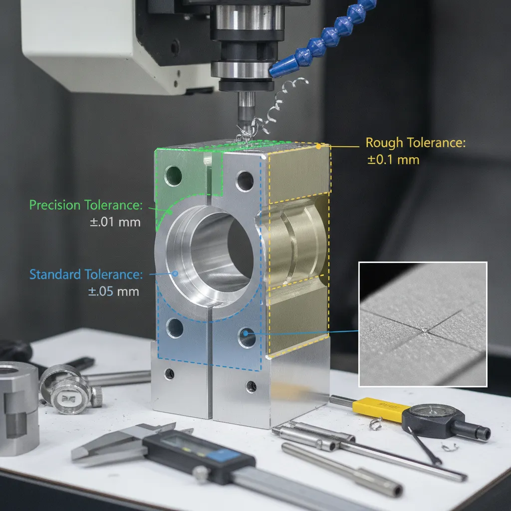
Tight tolerances begin at ±0.025 mm. Precision tolerances drop to ±0.005 mm or below, the range where surface finish, thermal expansion, and fixturing all start to influence the outcome. Here is the practical hierarchy:
- Standard (ISO 2768-m): ±0.1 mm, suitable for non-critical fits and general geometry
- Tight: ±0.025 mm, required for sliding fits, close clearances, and functional mating surfaces
- Precision: ±0.005 mm and below, bearing bores, sealing surfaces, and high-load assemblies
Leaving a bearing bore at ±0.1 mm causes press-fit failure or bearing play. Specifying ±0.01 mm on a cosmetic face drives up cycle time and inspection cost with no functional benefit. Both are production problems, just at opposite ends.
What Is Tolerance Stack-Up Analysis and How Do Cumulative Tolerances Affect Multi-Operation CNC Processes?
Tolerance stack-up occurs when individual feature tolerances accumulate across an assembly, producing a worst-case error larger than any single tolerance suggests. In a part with five features each held to ±0.05 mm, the worst-case cumulative error reaches ±0.25 mm, enough to cause assembly interference or misalignment. For a detailed walkthrough of stack-up calculation methods, see our Precision Tolerance Stackup: A Complete Guide.
Stack-up risk is highest in multi-operation parts where datum shifts between setups introduce additional variation. Identifying your assembly’s critical closing dimension before setting individual feature tolerances prevents this.
How Do You Balance Part Quality with Manufacturing Feasibility When Setting Tolerances?
A 3-step selection framework keeps tolerance decisions grounded in function rather than assumption:
- Identify the functional requirement driving each dimension, ask what breaks or fails if this feature is out of spec.
- Verify achievability, confirm the specified tolerance is realistic for the material and process. Hard alloys and thin walls constrain what any machine can hold repeatably.
- Check stack-up risk, confirm the tolerance doesn’t accumulate with adjacent features to exceed the assembly’s functional limit.
ISO 9001:2015-certified shops document tolerance verification at each operation, creating an auditable record that medical device and automotive buyers require. At MFG SOLUTION, every part moves through full process control under ISO 9001:2015, ISO 13485:2016, and IATF 16949, so tolerance conformance is recorded at each stage, not just at final inspection. Learn more about how certification shapes our process in our ISO 9001 precision machining content.
How Tolerances Affect CNC Machining Cost, Lead Time, and Material Selection
Tighter tolerances cost more, take longer, and constrain your material options, the relationship is non-linear, and the steepest cost jumps happen at the precision end of the scale.
What Is the Relationship Between Tolerance Tightness and Pricing in CNC Machining?
CNC machining tolerance standards don’t scale in price proportionally. Moving from ±0.1 mm to ±0.05 mm is a modest cost increase, slower feeds, an extra inspection pass, perhaps one additional setup. But tightening from ±0.1 mm to ±0.025 mm typically raises per-part cost by 25–50% due to reduced cutting speeds, additional fixturing, and extended inspection time. Tighten further to ±0.005 mm and cost can double or triple again, because that range often requires grinding, lapping, or 100% CMM inspection at every operation.
This is the tolerance-cost curve in practice: the relationship is exponential, not linear. The jump from ±0.01 mm to ±0.005 mm is far more expensive than the jump from ±0.1 mm to ±0.05 mm, even though both represent the same 0.05 mm reduction on paper.
Material selection compounds this. Plastics are manageable at tolerances above ±0.05 mm, but tighter plastic tolerances require climate-controlled machining environments to counteract thermal expansion, adding facility overhead and time. Steel and aluminum hold tight tolerances more predictably, making them the practical choice when your design calls for sub-±0.025 mm features.
How Do Tighter Tolerances Impact Production Lead Times and Part Cost?
Parts produced to ISO 2768-m (medium) standard tolerances can typically ship within 3–5 days. Precision parts requiring grinding, lapping, or CMM inspection at every operation add 3–7 days to that schedule, sometimes more when specialized equipment is queued.
At MFG SOLUTION, standard-tolerance small precision parts up to 38mm diameter ship within 3 days of order approval. Parts with tighter specifications are quoted individually, with lead time adjusted based on the inspection and process requirements the drawing actually demands.
The most practical cost-reduction step available before quoting is a drawing audit. Many designs carry tight tolerances on non-critical features, a clearance hole held to ±0.01 mm when ±0.1 mm would function identically. A DFM review catches these over-toleranced features early, before they inflate machine time and inspection costs. Submitting a drawing with unnecessary precision requirements is one of the most common sources of avoidable cost in precision part sourcing.
What Is GD&T and How Does It Integrate with CNC Tolerance Standards?
GD&T (Geometric Dimensioning and Tolerancing) is a symbolic language that controls form, orientation, location, and runout on engineering drawings, going beyond what coordinate tolerances alone can define.
Governed by ASME Y14.5-2018 in North America and ISO 1101 internationally, GD&T addresses characteristics like flatness, perpendicularity, and true position that a simple ±X.XX mm callout cannot fully constrain. Traditional coordinate tolerancing tells a machine where a feature should be; GD&T defines the exact geometric zone within which that feature must fall. Understanding how GD&T integrates with CNC machining tolerance standards is essential for any engineer working on precision assemblies.
How Does GD&T Improve Upon Traditional Tolerance Methods?
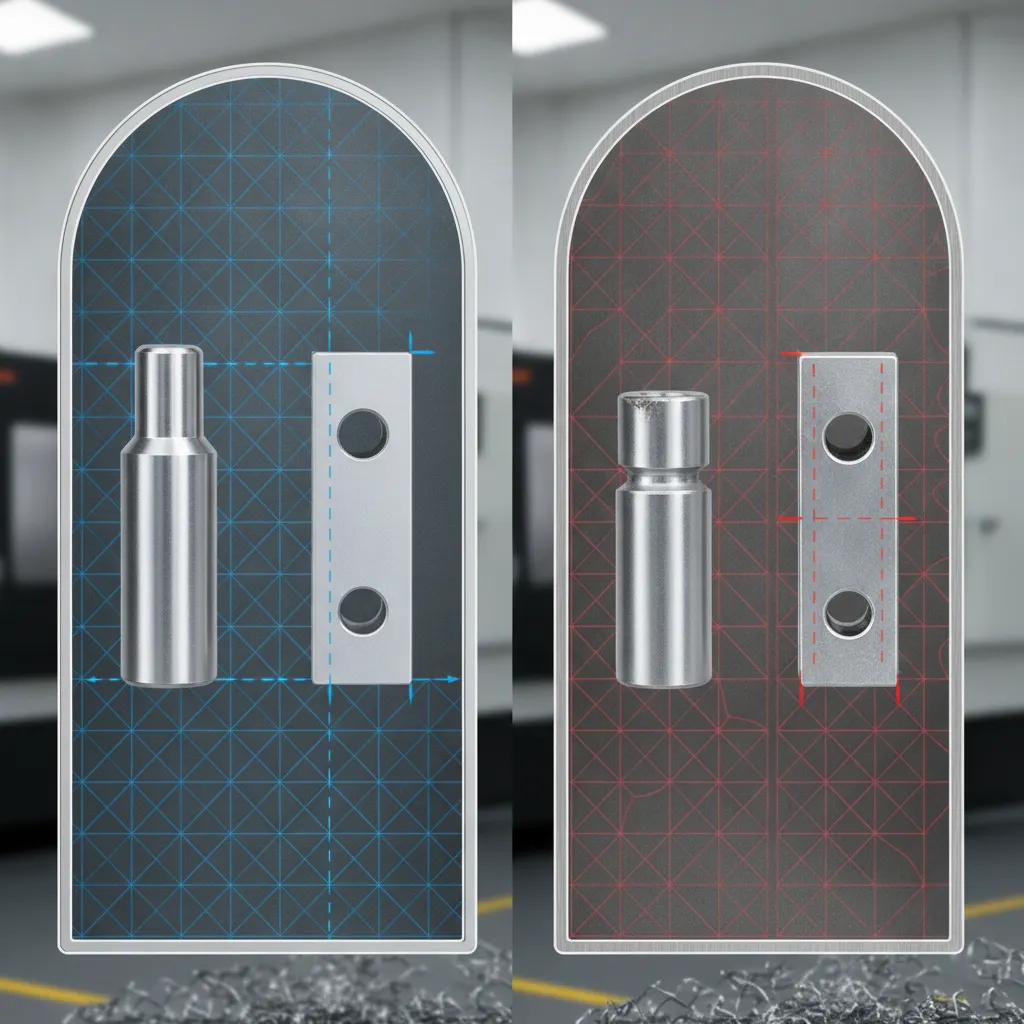
The difference becomes concrete with bolt-hole patterns. A ±0.05 mm coordinate tolerance allows each hole to shift independently along two axes, creating a square tolerance zone. A GD&T true position callout of ⌀0.1 mm defines a circular zone instead, which is 57% larger in usable area. That means GD&T often permits more manufacturing variation while still guaranteeing the holes align correctly at assembly.
This is not just a geometric curiosity. Tighter coordinate tolerances drive up machining cost; a well-placed GD&T callout can relax the actual manufacturing requirement without compromising fit or function.
GD&T and ISO 2768 can coexist on the same drawing, ISO 2768 sets default tolerances for undimensioned features, while GD&T callouts override specific critical features. This combination is common practice on production drawings that mix general geometry with precision interfaces.
When Should You Use GD&T Instead of Standard ISO Tolerance Specifications?
ISO 2768 alone is sufficient for general machined parts with no critical assembly interfaces. GD&T becomes necessary when a drawing controls mating surfaces, bearing seats, seal faces, or any feature where form error directly affects function.
GD&T is also mandatory for IATF 16949 automotive and ISO 13485 medical device drawings, both standards require documented geometric controls that coordinate tolerancing cannot provide. Shops certified to these standards and equipped with 5-axis CNC machines and CMM inspection capability, such as MFG SOLUTION, are built to interpret and verify GD&T callouts across production runs.
When specifying CNC machining tolerance standards on a new drawing, the decision rule is straightforward: use ISO 2768 as your baseline, then layer GD&T only where assembly fit, sealing, or regulatory compliance demands it.
“GD&T is not a replacement for sound tolerance engineering — it is a precision tool that, when applied correctly, can simultaneously reduce manufacturing cost and improve assembly reliability. The key is knowing which features truly require geometric control and which do not.” — Alex Krulikowski, Author and GD&T Consultant, Effective Training Inc.
Frequently Asked Questions
What tolerance class should I specify if I don’t call out tolerances on my CNC drawing?
If no tolerances are specified, most machine shops default to ISO 2768-m (medium class) for linear dimensions and ISO 2768-K for geometric tolerances. Medium class covers linear dimensions up to ±0.1 mm for features between 6 mm and 30 mm, which suits general-purpose parts. For tighter assemblies—particularly in automotive or medical applications—explicitly specify ISO 2768-f (fine) or call out individual feature tolerances using GD&T to avoid ambiguity and rework.
Can CNC machining hold tolerances tighter than ±0.005 mm, and what processes achieve this?
Yes, CNC machining can hold tolerances tighter than ±0.005 mm on specific features using the right process and setup. Swiss lathe machining is particularly effective for small-diameter parts, holding tolerances down to ±0.002 mm or finer on turned diameters. 5-axis CNC milling with rigid fixturing and temperature-controlled environments can achieve similar results on complex geometries. These capabilities require careful tool selection, reduced cutting speeds, and post-process inspection with CMM equipment to verify conformance.
How does ISO 2768 apply to threaded features and drilled holes specifically?
ISO 2768 does not directly govern threaded features, thread tolerances fall under ISO 965 for metric threads, which defines tolerance classes such as 6H for internal threads and 6g for external threads. For drilled holes, ISO 2768 linear tolerances apply to the hole’s positional dimension, but the hole diameter itself is typically controlled by ISO 286-1 tolerance grades (IT grades). Always specify thread class and hole fit grade separately on your drawing.
What is the difference between unilateral and bilateral tolerances in CNC machining?
A unilateral tolerance allows variation in only one direction from the nominal dimension, for example, +0.00 / −0.02 mm, while a bilateral tolerance permits variation in both directions, such as ±0.01 mm. Unilateral tolerances are common for shaft-to-bore fits where one boundary is critical. Bilateral tolerances suit symmetric features where equal deviation in either direction is acceptable. Choosing the right type directly affects fit, function, and machining cost.
How do I verify that my supplier is actually meeting the CNC machining tolerance standards specified on my drawing?
Verification begins with requiring a First Article Inspection (FAI) report or a dimensional inspection report with actual measured values for all critical features. Reputable suppliers will use Coordinate Measuring Machines (CMM) and provide documented evidence of conformance. For ongoing production, request Statistical Process Control (SPC) data or periodic inspection records. Suppliers certified to ISO 9001:2015, IATF 16949, or ISO 13485 are required to maintain documented tolerance verification at each production stage, giving buyers an auditable quality trail.
Conclusion
Tolerance standards are not bureaucratic overhead, they are the specification language that connects your design intent to a machined part that actually works. Applying CNC machining tolerance standards correctly from the earliest stage of drawing preparation prevents costly rework, supplier ambiguity, and assembly failures downstream. Three things are worth acting on: first, default to ISO 2768-m only when your application genuinely allows it; second, match your tolerance class to the fit system (ISO 286-1) before you finalize a drawing; third, flag any feature requiring tighter than ±0.01 mm early, because process selection, Swiss lathe, 5-axis milling, or grinding, must be decided before quoting, not after.
If you have a drawing ready, submit it to MFG SOLUTION for a quote within 8 hours. Include your required tolerance class and material, and our engineering team will confirm process feasibility before production begins.
Recommended Articles
Explore more from our content library: