
2026-05-03
CNC Hole Drilling: How the Technology Really Works

| Key Insight | Explanation |
|---|---|
| CNC drilling is computer-controlled | G-code programs direct spindle speed, feed rate, and depth automatically, eliminating manual positioning errors. |
| Multiple drilling types exist | From spot drilling to deep-hole gun drilling, each technique suits specific depth-to-diameter ratios and tolerance requirements. |
| Deep-hole drilling requires specialized tooling | Holes with a depth-to-diameter ratio above 10:1 demand gun drills, BTA drills, or peck-drilling cycles to manage chip evacuation. |
| Tolerances can reach ±0.005mm | Modern 5-axis CNC machines and rigid setups allow hole positions and diameters to be held to very tight tolerances. |
| Coolant management is critical | Internal coolant delivery and correct chip evacuation strategies directly affect surface finish, tool life, and dimensional accuracy. |
| Certification standards govern quality | ISO 9001:2015, ISO 13485:2016, and IATF 16949 set the quality management benchmarks for precision drilled components in medical and automotive sectors. |
CNC hole drilling technology is a computer-controlled subtractive machining process in which a rotating drill bit creates precise, repeatable holes in a stationary workpiece. Unlike manual drilling, every axis movement, spindle speed, and feed rate is governed by G-code, which eliminates human positioning error. The result is consistent hole geometry across hundreds or thousands of parts. In this article you’ll learn exactly how the process works, which drilling method suits your application, what mistakes to avoid, and how to get the best results in 2026.
Precision holes are everywhere: fastener bores in aerospace frames, coolant channels in automotive engine blocks, fluid ports in medical implants, and connector holes in electronics housings. Getting them right the first time matters enormously. A mislocated hole or a rough bore wall can scrap an expensive part or, worse, cause a field failure. That’s why understanding CNC hole drilling technology is essential for any engineer or procurement professional sourcing precision components. [1]
What Is CNC Hole Drilling Technology?
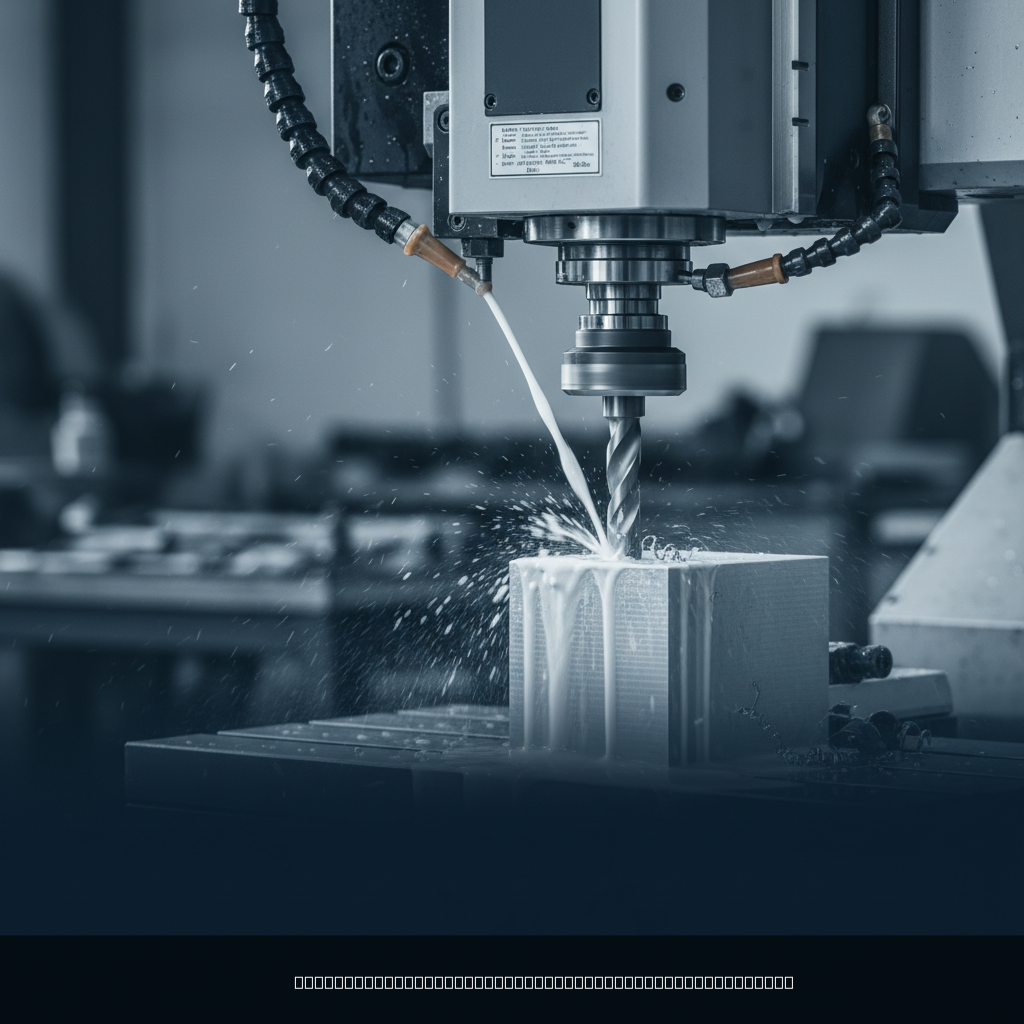
CNC hole drilling technology is a fully automated machining method that uses computer-programmed instructions to drive a rotating cutting tool into a workpiece, producing cylindrical holes with precise diameter, depth, position, and surface finish. It applies to metals, plastics, composites, and wood, and it scales from micro-holes measured in micrometers to large-diameter bores over 100mm.
The Core Definition
At its simplest, drilling is a fundamental machining operation that creates holes using a rotating cutting tool called a drill bit. [2] The “CNC” prefix changes everything: a computer numerical control system reads a part program, moves the spindle to exact X-Y coordinates, plunges to a specified Z-depth, and retracts, all without human intervention mid-cycle.
This automation matters for three reasons:
- Repeatability: Every hole lands at the programmed position, typically within ±0.01mm or better.
- Speed: CNC machines can execute dozens of holes per minute with automatic tool changes.
- Documentation: Modern controllers log spindle load, feed rate, and cycle time, creating an auditable quality record.
Why It Matters Across Industries
According to Xometry’s technical resources, CNC drilling technology is used to create precision holes in aircraft structures including wings, fuselages, and engine components like turbine housings. [3] The medical device sector relies on it equally. Bone screws, catheter fittings, and implant housings all require holes that meet ISO 13485:2016 quality standards, where even a 0.02mm deviation can cause a device to fail regulatory inspection.
Automotive suppliers face similar demands. IATF 16949, the automotive quality management standard, requires full process control and traceability for every critical characteristic, including hole dimensions. A procurement manager sourcing brake caliper components, for example, can’t afford bore diameters that drift between batches.
Pro Tip: Always specify hole tolerances, surface roughness (Ra), and true position callouts on your technical drawing before requesting a quote. Vague specs lead to vague prices and inconsistent parts. Clear drawings cut quoting time and reduce back-and-forth significantly.
How CNC Hole Drilling Technology Works
CNC hole drilling works by translating a CAD model into G-code instructions that control spindle rotation, axis movement, feed rate, depth, and coolant delivery in a precise, repeatable sequence. The machine executes this program identically on every part in a batch.
The Step-by-Step Drilling Process
- CAD/CAM programming: An engineer designs the part in CAD software. CAM software converts hole features into G-code, specifying canned drilling cycles (e.g., G81 for standard drilling, G83 for peck drilling).
- Workholding setup: The workpiece is clamped in a vise, fixture, or collet. Rigid workholding prevents vibration that causes hole wander or chatter marks.
- Tool selection and loading: The correct drill geometry is loaded into the spindle or tool changer. Drill geometry, point angle, helix angle, and coating all affect performance in a given material. [4]
- Spot drilling (optional): A spot drill or center drill creates a small conical indent at each hole location. This prevents the full drill from “walking” on the surface at the start of the cut. [5]
- Drilling cycle execution: The CNC controller moves the spindle to the X-Y position, activates coolant, ramps to programmed RPM, and feeds the drill to the target depth at the programmed feed rate (measured in mm/rev or in/rev).
- Chip evacuation: For deeper holes, peck drilling cycles retract the drill periodically to break and clear chips. Inadequate chip clearance is one of the most common causes of drill breakage.
- Inspection: Hole diameter, depth, position, and surface finish are verified with go/no-go gauges, CMM (coordinate measuring machine) probes, or bore gauges.
Key Parameters That Control Hole Quality
Two parameters dominate drilling outcomes: cutting speed (surface speed in m/min) and feed rate (advancement per revolution). Getting both right for the workpiece material is non-negotiable.
| Parameter | Typical Range | Effect on Quality |
|---|---|---|
| Spindle speed (RPM) | 500–20,000+ RPM | Too high: tool wear, burn. Too low: poor surface finish, chatter. |
| Feed rate (mm/rev) | 0.01–0.5 mm/rev | Too high: drill deflection, oversize holes. Too low: rubbing, work hardening. |
| Coolant pressure (bar) | 5–150 bar (internal) | Higher pressure flushes chips more effectively in deep holes. |
| Peck depth increment | 0.5–3× drill diameter | Smaller increments improve chip control in deep or gummy materials. |
| Point angle | 90°–140° | 118° is standard for steel; 135° split-point reduces thrust in hard alloys. |
Research from Harvey Performance’s technical library confirms that drill geometry choices, specifically helix angle and web thickness, directly determine chip formation behavior and hole surface quality. [4] Thin-web drills reduce thrust force and are preferred for small-diameter holes in hardened steels.
Types of CNC Drilling Operations
CNC hole drilling technology covers several distinct operation types, each designed for a specific hole geometry, depth, or accuracy requirement. Choosing the wrong type wastes time and money.
Standard and Specialty Drilling Methods
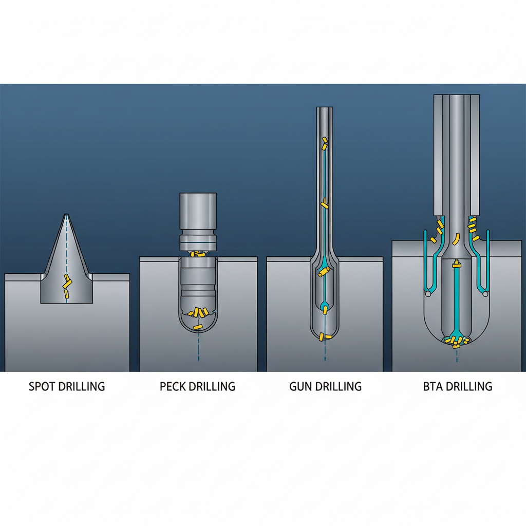
- Spot drilling: A short, rigid drill creates a starter divot to guide the full drill. Essential for holes on curved or inclined surfaces. [5]
- Through drilling: The drill passes completely through the workpiece. Exit burr control is a common challenge.
- Blind hole drilling: The drill stops at a programmed depth. Flat-bottomed blind holes require specialized parabolic or flat-end drills.
- Peck drilling (G83 cycle): The drill advances in increments and retracts to clear chips. Used for holes deeper than 3× the drill diameter. [6]
- Deep-hole drilling: Defined as holes with a depth-to-diameter (L/D) ratio of 10:1 or greater. Requires dedicated equipment or specialized cycles. [7]
- Gun drilling: A single-flute drill with internal coolant delivery drills very straight, deep holes. Common in mold making, hydraulic manifolds, and barrel manufacturing.
- BTA (Boring and Trepanning Association) drilling: A multi-flute tool with external chip evacuation, used for large-diameter deep holes. [8]
- Micro-drilling: Drill diameters below 1mm, used in electronics and medical devices. Requires high-speed spindles (up to 60,000 RPM) and vibration-free setups. [3]
- Reaming: A finishing operation that follows drilling to achieve tight diameter tolerances (IT6–IT7) and fine surface finishes (Ra 0.4–1.6 µm).
Deep-Hole Drilling: A Special Case
Deep-hole drilling deserves particular attention. JBC Machine’s technical analysis notes that CNC deep hole drilling involves creating holes with an L/D ratio of 10:1 or greater, and this process requires specialized equipment to manage heat, chip evacuation, and drill deflection simultaneously. [7]
The SME (Society of Manufacturing Engineers) has documented that today’s deep-hole drilling machines are highly engineered turnkey systems that ensure process stability far beyond what simple gundrilling machines offered a decade ago. [9] As of 2026, many deep-hole systems integrate real-time torque monitoring and adaptive feed control to prevent drill breakage automatically.
Key Benefits of CNC Hole Drilling Technology
CNC hole drilling technology delivers measurable advantages over manual or conventional drilling in precision, speed, repeatability, and cost-per-part at volume. These benefits compound as batch sizes increase.
Precision and Repeatability
The most obvious benefit is accuracy. CNC machines position holes to within ±0.005mm of nominal in favorable conditions. Manual drilling, by contrast, typically achieves ±0.1–0.5mm at best. For a medical device with six fluid ports that must align with a mating manifold, that difference is the gap between a functioning device and a failed assembly.
- Positional accuracy: Modern CNC machining centers achieve true position tolerances of ±0.01mm or tighter, verified by CMM inspection.
- Diameter consistency: Controlled feed rates and sharp tooling hold hole diameters within H7 tolerance (a standard fit class) across entire production runs.
- Surface finish: Properly programmed CNC drilling achieves Ra 1.6–3.2 µm without secondary operations. Reaming after drilling reaches Ra 0.4 µm.
Speed, Cost, and Scalability
For batch production, CNC drilling is dramatically faster than manual methods. A CNC machining center can complete an automatic tool change in under two seconds and reposition between holes in milliseconds. This speed translates directly into lower cost-per-part at volume.
- Reduced labor: One operator can monitor multiple CNC machines simultaneously, reducing direct labor cost per part.
- Lower scrap rates: Consistent parameters mean fewer out-of-tolerance holes and less rework. Industry analysts suggest scrap rate reductions of 30–60% compared to manual drilling when switching to CNC.
- Scalability: The same G-code program that drills 10 prototype parts drills 10,000 production parts identically.
- Traceability: CNC controllers log cycle data that supports ISO 9001:2015 process documentation requirements.
At MFG SOLUTION, we’ve found that customers transitioning from manual or semi-automatic drilling to our CNC Mill & Turn and CNC Turning services consistently reduce their per-part cost by 20–40% on runs above 500 pieces, while simultaneously tightening their tolerance bands.
Pro Tip: If your part requires multiple hole diameters, consider a CNC Mill & Turn setup that combines turning and drilling in a single clamping. Every re-clamping introduces positional error. Fewer setups mean tighter true position tolerances and faster cycle times.
Common Challenges and Mistakes in CNC Drilling
CNC hole drilling technology is powerful, but several recurring challenges trip up even experienced machinists and engineers. Recognizing these pitfalls early saves significant rework cost.
Drill Wandering and Positional Error
Drill wander occurs when the drill tip deflects from its intended path at the start of the cut. It’s one of the most common defects in CNC drilling. Contributing factors include:
- Skipping spot drilling on smooth or curved entry surfaces
- Excessive drill overhang (length-to-diameter ratio above 5:1 without support)
- Dull or asymmetrically worn drill lips
- Insufficient workholding rigidity, particularly in thin-walled parts
A common mistake in small-part machining is using a standard twist drill for the full hole depth on diameters below 3mm without spot drilling first. The result is a hole that’s off-position by 0.05–0.2mm, which fails true position callouts on precision assemblies. [10]
Chip Evacuation and Tool Breakage
Chip packing is the leading cause of drill breakage, especially in deep holes and gummy materials like stainless steel, titanium, and certain aluminum alloys. When chips pack in the flutes, cutting forces spike suddenly and the drill snaps.
- Peck drilling cycles are the first line of defense. Retracting the drill every 1–3 diameters of depth clears chips before they pack. [6]
- Internal coolant delivery at high pressure (70–150 bar) flushes chips directly from the cutting zone in deep-hole applications.
- Chip breaker geometries on modern drills segment chips into shorter lengths that evacuate more easily.
One pitfall to watch for: using flood coolant alone on deep holes. Flood coolant cools the outside of the drill but doesn’t reach the cutting tip effectively once the hole depth exceeds 3× the drill diameter. Internal coolant through-tool delivery is the correct solution at those depths. [7]
Research from LTC Proto’s technical blog confirms that timing of peck retract cycles is critical: retracting too infrequently allows chip accumulation, while retracting too often adds unnecessary cycle time without improving chip control. [6]
Surface Finish and Tolerance Failures
Poor surface finish inside a drilled hole usually traces back to one of three causes:
- Worn tooling with chipped cutting edges
- Incorrect feed rate (too high causes tearing; too low causes rubbing and work hardening)
- Vibration from inadequate workholding or excessive spindle runout
Tolerance failures, specifically oversize holes, are often caused by drill runout. A drill running with 0.02mm radial runout produces a hole 0.04mm oversize because it cuts on both sides of the nominal diameter. Checking and minimizing spindle and holder runout is a non-negotiable step before precision drilling operations.
Best Practices for CNC Hole Drilling in 2026
Effective CNC hole drilling in 2026 combines proven machining fundamentals with modern tooling, adaptive control systems, and disciplined process documentation. Here’s what the best shops do consistently.
Tooling, Setup, and Programming Fundamentals
- Match drill geometry to material: Use 118° point angles for soft metals and plastics; 135° split-point for hardened steels and stainless; parabolic flutes for deep holes in aluminum.
- Use hydraulic or shrink-fit holders: These minimize runout to below 0.003mm, which directly improves hole diameter accuracy and surface finish.
- Program spot drills first: Always spot drill on inclined, curved, or interrupted surfaces. MakerVerse’s design guidelines confirm spot drilling is the initial step in many CNC drilling sequences for good reason. [5]
- Apply appropriate canned cycles: G81 for standard through-holes, G82 for counter-boring with dwell, G83 for deep peck drilling. Using the right cycle reduces programming errors and optimizes chip control.
- Verify with simulation: CAM simulation catches tool collision, incorrect depth, and wrong tool selection before the machine runs. This is standard practice in any ISO 9001:2015 certified shop.
Quality Control and Process Documentation
Quality doesn’t happen by accident. It’s built into the process through measurement and documentation.
- First-article inspection (FAI): Measure every hole feature on the first part before running the full batch. CMM verification of true position, diameter, and depth catches setup errors before they multiply.
- Statistical process control (SPC): For high-volume runs, track hole diameter measurements over time to detect tool wear trends before parts go out of tolerance.
- Tool life management: Set conservative tool change intervals based on material and hole count. A worn drill costs far less than a batch of scrapped parts.
- Coolant concentration checks: Correct coolant concentration (typically 6–10% for water-soluble coolants) maintains lubricity and prevents bacterial growth that degrades cutting performance.
Our team at MFG SOLUTION recommends that customers specify surface roughness requirements (Ra value) and tolerance class (H7, H8, etc.) explicitly on drawings. Vague callouts like “smooth finish” or “tight tolerance” create ambiguity that leads to parts that technically pass inspection but don’t function as intended in assembly.
Pro Tip: For parts requiring holes in multiple faces, a 5-axis CNC machining center can drill all features in a single setup. This eliminates the positional error introduced by re-clamping and cuts total cycle time by 30–50% compared to multi-setup 3-axis approaches. Ask your supplier whether 5-axis capability is available for your geometry.
As of 2026, adaptive feed control systems that read spindle torque in real time are increasingly standard on production CNC machines. These systems automatically reduce feed rate when cutting forces spike, preventing drill breakage without operator intervention. This technology is particularly valuable for unattended overnight production runs. [9]

Sources & References
- EngineeringTechnology.org, “Drilling and Holemaking,” 2024
- Goodwin University, “7 Essential CNC Machining Techniques,” 2024
- Xometry, “CNC Drilling Services,” 2026
- Harvey Performance, “Mastering CNC Drilling: Geometries and Key Factors,” 2024
- MakerVerse, “Best Practices: Designing for CNC Drilling,” 2024
- LTC Proto, “Learn The Basics of Deep Hole Drilling with Your CNC Machine,” 2024
- JBC Machine, “Deep Hole Drilling with CNC: Techniques, Challenges, and Solutions,” 2024
- SmartLathe, “Common Types of CNC Horizontal Deep Hole Drilling,” 2024
- SME (Society of Manufacturing Engineers), “Deep-Hole Drilling Continues to Evolve,” 2023
- YO! Asmbly Community, “Drilling on the Small CNC — Possible? Advisable?,” 2023
- Europe PMC, “CNC Deep Hole Drilling with the Quadruple Zone Technique,” 2022
- 3ERP, “What is CNC Drilling: Definition, Types, Applications, Machines,” 2024
- Kent CNC, “CNC Deep Hole Drilling & Gun Drilling: Precision Solutions,” 2024
Frequently Asked Questions
1. What is CNC hole drilling technology, and how does it differ from manual drilling?
CNC hole drilling technology is a computer-controlled process where G-code programs direct a rotating drill bit to create holes at precise locations, depths, and diameters automatically. Manual drilling relies on operator skill and physical positioning, which introduces variability. CNC drilling achieves positional accuracy of ±0.005–0.02mm, while manual drilling typically achieves ±0.1–0.5mm. For production runs of 50 or more parts, CNC drilling is faster, more consistent, and more cost-effective.
2. What is the difference between standard drilling and deep-hole drilling?
Standard CNC drilling covers holes with a depth-to-diameter (L/D) ratio below 10:1. Deep-hole drilling applies to L/D ratios of 10:1 or greater, and it demands specialized techniques like gun drilling, BTA drilling, or peck drilling cycles with high-pressure internal coolant. Deep holes are more prone to drill deflection, chip packing, and heat buildup, so standard tooling and parameters simply don’t work reliably at those depths.
3. What materials can CNC hole drilling technology process?
CNC hole drilling technology processes virtually any machinable material: aluminum alloys, stainless steel, carbon steel, titanium, brass, copper, engineering plastics (PEEK, Delrin, nylon), and composites. Each material requires specific drill geometry, cutting speed, feed rate, and coolant strategy. Titanium, for example, requires lower cutting speeds, higher feed rates, and aggressive coolant to prevent work hardening and built-up edge on the drill.
4. What tolerances can CNC drilling achieve?
Standard CNC drilling achieves hole diameter tolerances in the IT9–IT10 range (roughly ±0.02–0.05mm for small diameters). Adding a reaming operation after drilling improves this to IT6–IT7 (±0.005–0.015mm) with surface finishes of Ra 0.4–1.6 µm. True position tolerances of ±0.01mm are achievable on well-maintained CNC machining centers with proper workholding. Results vary depending on material, hole depth, and machine condition.
5. How does peck drilling work, and when should you use it?
Peck drilling is a CNC canned cycle (typically G83) that advances the drill a programmed increment, retracts to clear chips, then advances again. You should use it whenever a hole depth exceeds 3 times the drill diameter, when machining materials that produce long stringy chips (stainless steel, aluminum), or when drilling without internal coolant-through tooling. The peck increment is typically set to 0.5–2 times the drill diameter, with smaller increments for harder or gummier materials.
6. What certifications should a CNC drilling supplier hold for medical or automotive parts?
For medical device components, suppliers should hold ISO 13485:2016 certification, which governs quality management systems for medical device manufacturing. For automotive parts, IATF 16949 is the relevant standard, covering process control, traceability, and defect prevention. ISO 9001:2015 is the baseline quality management standard applicable across all industries. A supplier holding all three certifications demonstrates documented process control and the ability to support regulatory audits.
7. How do I choose between CNC drilling and EDM (electrical discharge machining) for small holes?
CNC hole drilling technology is faster and less expensive for most standard hole geometries in machinable materials. EDM is the better choice for holes below 0.3mm diameter, holes in hardened steels above 60 HRC that are difficult to drill, or non-circular hole profiles. For precision round holes in soft to medium-hard materials at diameters above 0.5mm, CNC drilling with reaming is almost always the more cost-effective solution.
8. What should I include in a technical drawing to get an accurate CNC drilling quote?
Include hole diameter with tolerance (e.g., 6.0 +0.015/0.000mm), depth (through or blind with exact depth), true position callout (e.g., ⌀0.02mm), surface roughness (Ra value in µm), material specification, and any secondary operations like reaming, tapping, or countersinking. The more specific your drawing, the faster and more accurate your quote will be. Vague notes like “drill to fit” or “smooth bore” delay quoting and often result in parts that don’t meet assembly requirements.
Conclusion
this approach sits at the foundation of precision manufacturing. Get it right and your parts assemble perfectly, pass inspection, and perform reliably in service. Get it wrong and you’re looking at scrap, rework, and delayed shipments.
The key takeaways are straightforward. Match your drilling method to your L/D ratio and material. Use spot drilling to prevent wander. Manage chips aggressively in deep holes. Specify tolerances and surface finish explicitly on your drawings. And choose a supplier with documented quality systems, not just a low price.
For small precision parts up to 38mm in diameter, MFG SOLUTION combines CNC Turning, Swiss Lathe, CNC Mill & Turn, and Automatic Lathe capabilities with ISO 9001:2015, ISO 13485:2016, and IATF 16949 certifications. Our 60+ engineering professionals quote within 8 hours and ship within 3 days. Whether you need a straightforward through-hole pattern or a complex multi-face drilling sequence on a difficult material, we have the equipment, the process documentation, and the quality track record to deliver parts that meet your specs the first time.
About the Author
Written by the Manufacturing – Precision Machining & CNC Services experts at MFG SOLUTION. Our team brings years of hands-on experience helping businesses with Manufacturing – Precision Machining & CNC Services, delivering practical guidance grounded in real-world results.
Recommended Articles
Explore more from our content library: