
2026-10-10
CNC Machining for Heat Exchanger Components: Manifolds, Ports, Thin Walls and Pressure Integrity
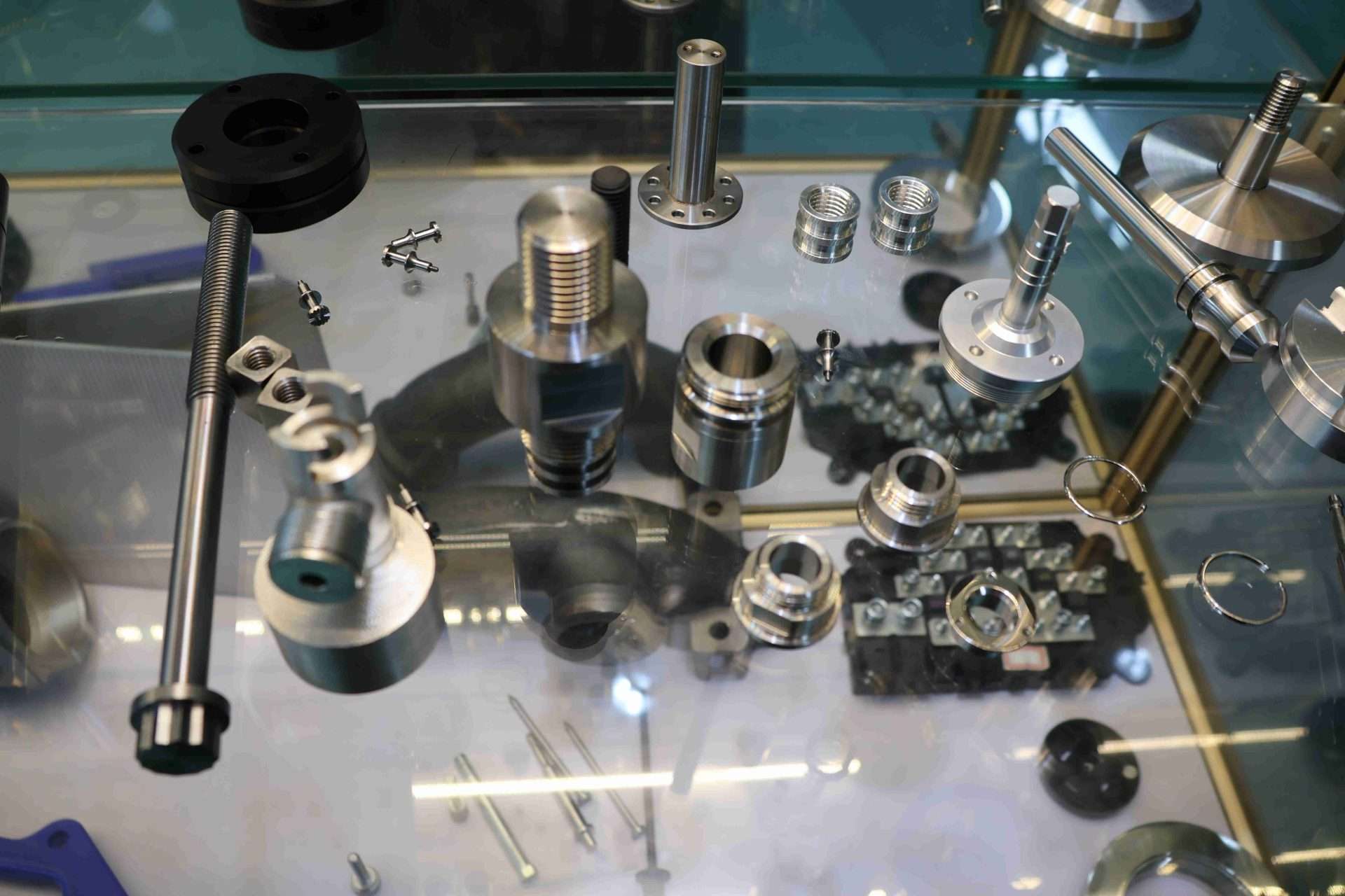

Heat exchangers are essential in industrial equipment that must transfer heat efficiently while maintaining reliable fluid flow. They are used in industrial cooling systems, hydraulic equipment, power generation, energy systems, chemical processing, refrigeration, and many other applications. Their performance depends not only on the heat-transfer element itself but also on the precision of the manifolds, end covers, mounting interfaces, port connections, and other machined components surrounding it.
CNC machining is particularly useful for heat exchanger components that require accurate sealing surfaces, precisely positioned ports, complex internal passages, controlled wall thicknesses, and repeatable assembly interfaces. It allows manufacturers to produce custom geometries from aluminum, stainless steel, and other suitable materials without committing to dedicated production tooling for every design.
However, heat exchanger components can be challenging to manufacture. A port may need to align with an internal passage. A sealing face must mate correctly with a gasket or another component. Thin walls can deform during machining, and a small dimensional error may affect assembly or create a leakage risk. Material selection, machining strategy, inspection, and pressure testing must therefore be considered together.
This guide explains how to approach CNC machining for heat exchanger components, which features deserve the most attention, how to select materials, and what engineering information to provide when requesting a quotation.
1. Why CNC Machining Matters for Heat Exchanger Components
Heat exchangers transfer thermal energy between fluids while keeping the fluids separated when the design requires it. Depending on the application, the system may use plates, tubes, compact passages, machined manifolds, or combinations of these elements.
CNC machining is often used for the precision components that connect, support, distribute, or seal the fluid circuits.
Typical machined components include:
- Fluid distribution manifolds
- Inlet and outlet blocks
- End plates and end covers
- Mounting brackets and support plates
- Threaded ports and connector interfaces
- Machined sealing faces and gasket grooves
- Sensor mounting blocks
- Custom housings and adapter plates
- Components with drilled or milled internal passages
These components may look relatively simple, but their functional requirements can be demanding. Port position, thread dimensions, sealing geometry, and flatness may affect the assembly and performance of the complete system.
CNC machining enables manufacturers to create these features from engineering drawings and three-dimensional models. The process can also accommodate design changes during prototype development, making it useful for custom equipment and low-volume production.
MFG SOLUTION provides CNC machining services for custom precision parts, with the manufacturing route evaluated according to geometry, material, tolerance requirements, finishing, and order quantity.
2. Common CNC-Machined Heat Exchanger Components
Understanding the function of each component helps engineers identify which dimensions and surfaces require the most attention.
2.1 Manifolds and Fluid Distribution Blocks
Manifolds distribute fluid between a supply connection and multiple passages or channels. Their geometry may include threaded ports, intersecting bores, counterbores, mounting holes, and sealing faces.
A manifold may be manufactured from a solid billet when its geometry and application justify machining from stock. This approach provides flexibility in passage layout and external geometry, although material removal and machining time can become significant for complex parts.
Important design considerations include:
- Port location and orientation
- Internal passage intersections
- Minimum wall thickness
- Thread specification and engagement
- Sealing-face geometry
- Tool access and chip evacuation
- Inspection access for critical features
Intersecting passages require special attention because their geometry may be difficult to inspect directly. Engineers should identify the critical dimensions and any cleanliness or internal-surface requirements before manufacturing begins.
For components with angled ports or features on several faces, 5-Axis CNC Machining may help reduce repositioning operations. However, conventional milling and drilling may be more economical for simpler designs.
2.2 Inlet and Outlet Ports
Ports connect the heat exchanger to the surrounding fluid system. They may use straight threads, tapered threads, flanges, face seals, or other connection standards depending on the equipment.
A port should not be defined only by its nominal diameter. The complete specification may need to include thread type, pitch, tolerance class, depth, sealing method, and the required relationship between the port and nearby features.
Mixing thread systems or leaving the sealing method unspecified can lead to assembly problems even when the nominal sizes appear similar.
For threaded features, consult the guide to accurately quoting threading services. The drawing should define the connection standard rather than relying on assumptions made during quotation.
2.3 End Plates and Covers
End plates and covers close or support sections of a heat exchanger assembly. Depending on the design, they may contain port openings, gasket grooves, bolt patterns, locating features, and machined sealing faces.
Flatness and hole-position accuracy can be important where the cover must mate evenly with another surface. A plate that is distorted during machining may require additional correction or fail to assemble correctly.
Material removal should be planned to manage stress and distortion, especially for larger plates or components with uneven wall thickness.
Where the cover includes multiple mounting faces, a well-planned CNC workholding strategy helps establish stable datums and maintain dimensional relationships between operations.
2.4 Sealing Interfaces and Gasket Grooves
Sealing interfaces deserve particular attention because surface geometry and finish can influence leakage performance.
Depending on the sealing system, critical characteristics may include:
- Surface flatness
- Surface roughness
- Groove width and depth
- Groove position
- Port-to-seal alignment
- Bolt-hole location
- Surface damage or burrs
The appropriate requirements depend on the specified gasket, seal material, operating pressure, temperature, fluid compatibility, and design standard.
A generic smooth finish does not automatically guarantee a reliable seal. The component must meet the requirements of the selected sealing system.
For additional background, review the CNC machining surface finish guide and the machining tolerances guide.
3. Selecting Materials for Heat Exchanger Components
Material selection influences thermal behavior, strength, corrosion resistance, weight, machinability, and cost. The best option depends on the fluid, operating environment, component function, and applicable design requirements.
3.1 Aluminum Alloys
Aluminum is commonly considered for lightweight housings, manifolds, mounting plates, and components used in applications where its thermal and mechanical properties are appropriate.
Its low density and good machinability can make it attractive for prototypes and production batches. Aluminum also supports complex pocketing and passage features, although deep cavities and thin walls require careful machining and workholding.
The alloy and temper must be specified. Different aluminum grades have different strength, corrosion behavior, machinability, and suitability for particular operating conditions.
The material should also be evaluated for compatibility with the working fluid and any required surface treatment.
See the aluminum material resource when comparing material options.
3.2 Stainless Steel
Stainless steel may be suitable where corrosion resistance, strength, or compatibility with a demanding environment is required.
It can be used for selected manifolds, connection blocks, mounting components, and other machined parts. The appropriate grade depends on the fluid chemistry, temperature, cleaning agents, chloride exposure, and mechanical loading.
Stainless steel can be more difficult to machine than many aluminum alloys. Work hardening, cutting forces, chip formation, and heat generation must be considered when selecting tools and machining parameters.
The choice should be based on the actual application rather than assuming all stainless steel grades provide equivalent performance.
For further information, consult the stainless steel block and machining guide.
3.3 Copper and Copper Alloys
Copper and selected copper alloys may be appropriate for applications that place particular importance on thermal or electrical conductivity.
However, machinability, strength, corrosion behavior, and fluid compatibility vary by alloy. Some copper alloys are easier to machine than others, and the material must satisfy the design requirements rather than conductivity alone.
Where the component uses copper or a copper alloy, the engineering team should confirm the exact grade, condition, surface requirements, and intended operating environment before production.
3.4 Engineering Plastics
Engineering plastics may be used for selected insulating, protective, mounting, or auxiliary components. Their suitability depends on temperature, fluid compatibility, mechanical loads, and dimensional stability.
Plastics generally behave differently from metals under temperature changes and mechanical loading. Their thermal expansion and creep behavior may influence clearances and long-term fit.
For relevant non-pressure-bearing applications, review the engineering plastics resource.
Important: Material suitability for a pressure-containing component must be established against the applicable design code, fluid, operating conditions, and customer requirements. A material’s machinability alone does not establish pressure-system suitability.
4. Machining Internal Passages, Ports and Cross-Holes
Internal fluid passages are among the most important manufacturing features in many heat exchanger manifolds and connection blocks.
The machining strategy depends on passage diameter, depth, orientation, geometry, required surface condition, and whether the passages intersect.
4.1 Drilling and Boring
Drilling is suitable for many straight passages and connection holes. For deeper holes, tool selection, chip evacuation, and alignment become increasingly important.
Boring may be used where a drilled feature needs additional dimensional control or a different surface condition.
The required process should be determined by the drawing and functional requirements rather than applying the same method to every hole.
For more information, see the CNC hole drilling guide and the CNC boring process guide.
4.2 Intersecting Passages
Manifolds may contain several intersecting holes that create a connected fluid network.
The location and angle of each passage influence the remaining wall thickness and the geometry of the intersections. If passages are positioned too close to an external face or another bore, the design may leave insufficient material.
Design reviews should consider the complete three-dimensional geometry, not just the individual hole dimensions.
Where the design permits, simplifying passage directions or standardizing hole sizes can reduce setup complexity and make manufacturing more predictable.
4.3 Internal Burrs and Cleanliness
Drilling and intersecting passages can create burrs inside a component. Loose chips or machining residue may also remain trapped in deep or intersecting channels.
These issues can be especially important when internal contamination could interfere with downstream equipment or fluid flow.
The drawing or manufacturing specification should identify the required deburring, cleaning, flushing, and inspection requirements. The method must be suitable for the component geometry and material.
Internal passages that cannot be inspected visually may require a defined cleaning process and an appropriate verification method.
5. Managing Thin Walls, Flatness and Distortion
Heat exchanger components may include thin covers, lightweight manifolds, deep pockets, narrow ribs, or uneven material sections. These features can make dimensional stability difficult to maintain.
During machining, cutting forces and clamping pressure can deform the workpiece. After the part is unclamped, it may spring back and produce dimensions different from those measured while it was held in the fixture.
5.1 Design Wall Thickness for Manufacturability
Thin walls can reduce weight and material use, but they also increase the risk of deflection and vibration.
The appropriate minimum wall thickness depends on the material, unsupported height, geometry, machining direction, clamping method, and functional requirements.
There is no universal minimum thickness suitable for every component.
Where possible, avoid unnecessarily tall, unsupported walls and narrow cavities that require long, flexible cutting tools. If the design must include thin sections, communicate their importance to the manufacturer during the design review.
The CNC part geometry optimization guide provides additional guidance on wall thickness, corner radii, and machining access.
5.2 Control Flatness on Covers and Sealing Faces
Flatness may be important on mating covers, gasket interfaces, and mounting surfaces.
A component with significant residual stress may change shape as material is removed. Uneven clamping can also distort the part during machining.
Potential controls include staged roughing and finishing, stable workholding, suitable material preparation, and final inspection after the part has been released from the fixture.
The correct strategy depends on the material, geometry, size, and specified tolerance.
5.3 Plan Multiple Setups Carefully
Every time a component is repositioned, the manufacturing process must re-establish its reference surfaces.
If a manifold has ports on several faces, datum planning helps maintain the required relationships between them.
Five-axis machining may reduce the number of setups for certain geometries, but it should be compared with simpler machining routes based on cost, access, accuracy, and actual feature requirements.
6. Surface Finish and Corrosion Protection
Surface treatment can affect corrosion resistance, wear, appearance, cleanliness, and dimensional fit. It should be considered as part of the complete manufacturing plan.
6.1 Surface Finish at Sealing Interfaces
A sealing face may require a specified surface roughness and flatness, depending on the seal design.
The manufacturer should identify which surfaces require special treatment and ensure the finishing process does not damage nearby threads, grooves, or locating features.
If a drawing calls for a particular roughness value, it should identify the relevant surface and measurement requirements clearly.
6.2 Anodizing and Other Treatments
Anodizing may be considered for suitable aluminum components, while passivation or other treatments may be appropriate for certain stainless steel parts.
Treatment choice depends on the material, working environment, corrosion requirements, and functional interfaces.
Coating thickness can affect dimensions and fits. Threads, sealing faces, electrical contacts, and locating surfaces may require special consideration or masking.
For general background, see the CNC machining surface finish guide.
6.3 Avoid Unspecified Cosmetic Requirements
Terms such as “smooth,” “polished,” or “corrosion resistant” can be interpreted differently by different suppliers.
Where performance depends on surface condition, specify the required finish, treatment, or acceptance criteria. Cosmetic requirements should be distinguished from functional requirements so that inspection and manufacturing effort are allocated appropriately.
7. Pressure Integrity, Leak Testing and Inspection
Machining accuracy and pressure integrity are related but distinct considerations.
A component may meet its dimensional drawing and still require additional verification before it can be accepted for a pressure-containing application. Conversely, a successful leak test does not prove that every dimension or material requirement has been satisfied.
The required verification depends on the complete assembly, operating conditions, design code, customer specification, and intended use.
7.1 Dimensional Inspection
Dimensional inspection may include measurements of:
- Port diameters and thread features
- Hole position and orientation
- Sealing-face flatness
- Groove width and depth
- Overall dimensions
- Critical wall thicknesses
- Mounting interfaces
The inspection method should be appropriate for the required tolerance and geometry. Conventional gauges may suit straightforward features, while a coordinate measuring machine may be useful for complex relationships.
For a broader quality framework, review 7 Quality Assurance Standards for CNC Machining Parts.
7.2 Leak Testing and Pressure Testing
Where required, leak testing or pressure testing should follow the applicable approved procedure and acceptance criteria.
The customer and manufacturer should agree on the test method, test medium, pressure or differential, duration, acceptance threshold, and documentation before testing begins.
Testing must be carried out using suitable equipment and safety controls. The procedure should not be improvised from the component’s nominal operating pressure alone.
If a part is only a mounting bracket or a non-pressure-bearing cover, a pressure test may not be applicable. The test requirement must reflect the actual function of the component.
7.3 Material Certificates and Traceability
Some applications require material certificates, batch identification, or records of secondary processes.
If traceability is required, specify the documentation and identification method at quotation stage. This helps ensure the manufacturing and inspection plan can meet the customer’s quality system.
See the ISO 9001 precision machining quality guide for more information on quality-system considerations.
8. Choosing Between CNC Machining and Alternative Processes
CNC machining is flexible, but it is not necessarily the lowest-cost process for every heat exchanger component.
The most suitable route depends on geometry, production quantity, tooling investment, material, and the amount of precision machining required after the initial manufacturing process.
CNC Machining
CNC machining is useful for prototypes, custom manifolds, small and medium production runs, and components with complex ports or precision interfaces.
It supports design changes without requiring dedicated forming tools for every geometry.
Casting Followed by CNC Machining
For suitable geometries and production volumes, casting may create a near-net-shape blank that reduces the amount of material removed during finishing.
Critical ports, sealing faces, and mounting features can then be machined to the required dimensions.
Precision casting may be worth evaluating where the geometry and production economics support it. The casting route must still meet the applicable material, quality, and inspection requirements.
Selecting the Economical Route
Compare total manufacturing cost rather than the machining rate alone. Relevant factors include:
- Material utilization
- Initial tooling investment
- Setup and programming
- Cycle time
- Secondary machining
- Surface treatment
- Inspection and testing
- Scrap and rework risk
- Expected production volume
The CNC machining cost analysis guide explains how these factors can affect a quotation.
9. Common Manufacturing Problems and How to Prevent Them
Problem 1: Port Standards Are Unclear
A drawing may show a nominal port size without defining the complete thread or sealing standard.
Prevention: Specify the connection standard, thread size and pitch, tolerance, depth, and sealing method.
Problem 2: Thin Walls Distort During Machining
Uneven material removal or excessive clamping can cause a component to move or spring back.
Prevention: Review wall thickness, datum selection, workholding, and the sequence of roughing and finishing operations.
Problem 3: Internal Burrs Remain in Fluid Passages
Intersecting holes can create burrs that are difficult to access.
Prevention: Define deburring and cleaning requirements and confirm how the manufacturer will verify the internal condition.
Problem 4: Sealing Faces Do Not Meet Requirements
A component may have the correct overall dimensions but still fail to meet the required flatness or surface finish.
Prevention: Identify critical sealing surfaces and specify their dimensional and surface requirements explicitly.
Problem 5: Surface Treatment Affects Critical Fits
Treatment thickness or process variation may affect threads and mating interfaces.
Prevention: Review finishing requirements before machining and identify any features that need masking or post-treatment verification.
Problem 6: Testing Requirements Are Added Too Late
Leak testing, pressure testing, or documentation may require additional planning, equipment, and time.
Prevention: Include the required test method, acceptance criteria, and reporting needs in the initial RFQ.
For additional manufacturing troubleshooting guidance, see Common CNC Machining Defects and How to Avoid Them.
10. How to Prepare an RFQ for Heat Exchanger Components
A complete RFQ allows the manufacturing team to evaluate geometry, material suitability, process options, inspection needs, and expected delivery requirements.
Include the following information wherever possible.
1. Engineering drawing
Provide a controlled drawing showing dimensions, tolerances, datums, threads, surface finishes, and critical interfaces.
2. 3D CAD model
A STEP file or another agreed CAD format helps the manufacturer review passage geometry, tool access, and machining setups.
3. Material specification
Identify the exact alloy or grade, condition, and any required material certification.
4. Operating conditions
Explain the intended function, fluid compatibility requirements, temperature range, and whether the component is pressure-bearing. Applicable design codes and customer specifications should be identified.
5. Surface treatment
State the required coating, anodizing, passivation, polishing, or other finishing operations, including any surfaces that must remain untreated.
6. Quantity and demand forecast
Provide prototype quantity, initial order quantity, expected repeat orders, and estimated annual demand if available.
7. Inspection and testing
Identify critical dimensions, required inspection reports, traceability requirements, and any approved leak or pressure testing procedure.
8. Delivery and packaging
State the required delivery schedule, destination, packaging conditions, and component identification requirements.
MFG SOLUTION provides an online quotation page for project submissions. For complex components, the engineering team may need to review the drawing and clarify operating and inspection requirements before confirming the manufacturing route and quotation.
You can also review how to source custom machined parts and how to reduce CNC machining costs without sacrificing part quality.
Frequently Asked Questions
1. Which heat exchanger components can be CNC machined?
Typical examples include manifolds, port blocks, end covers, mounting plates, adapter blocks, sensor mounts, and components with precision sealing interfaces. The appropriate process depends on geometry, material, quantity, and required tolerances.
2. Which material is best for a heat exchanger manifold?
There is no single best material. Aluminum may suit lightweight designs, stainless steel may be selected for specific corrosion or strength requirements, and copper alloys may be considered where thermal conductivity is important. Material compatibility must be evaluated against the fluid and operating environment.
3. Can CNC machining produce internal fluid passages?
Yes. Drilling, boring, and milling can create many internal passage geometries. The feasibility depends on passage diameter, depth, orientation, tool access, and the requirements for deburring, cleaning, and inspection.
4. Why are sealing surfaces important?
Sealing surfaces must meet the requirements of the selected gasket or seal system. Flatness, roughness, groove geometry, and alignment can influence sealing performance. The exact requirements depend on the design and operating conditions.
5. Does a dimensionally accurate part automatically pass a leak test?
No. Dimensional inspection and leak testing evaluate different characteristics. A component may meet its drawing but still require separate verification under the applicable test procedure.
6. How can thin-wall deformation be reduced?
The manufacturing strategy may include suitable workholding, balanced material removal, staged roughing and finishing, and inspection after unclamping. Design adjustments may also help where the application permits them.
7. Should heat exchanger components be pressure tested?
Only when required by the applicable design, code, customer specification, or approved quality plan. The required method and acceptance criteria must be established before testing, and testing must use suitable equipment and safety procedures.
8. What information should be included in a heat exchanger component RFQ?
Provide a 2D drawing, 3D CAD model, material specification, quantity, critical tolerances, surface treatment, operating environment, applicable pressure-system requirements, inspection documentation, and any required testing procedures.
Conclusion: Plan Precision Machining Around the Complete Fluid System
CNC machining can produce custom heat exchanger components with accurate ports, sealing interfaces, mounting features, and complex passage geometry. Achieving consistent results requires more than meeting individual dimensions: material selection, datum planning, wall thickness, surface condition, internal cleanliness, and inspection must all support the component’s intended function.
For OEMs and engineering teams, the most effective sourcing process begins with a complete drawing package and a clear description of the operating environment. Identifying pressure-related requirements and test procedures early helps prevent misunderstandings during manufacturing and final acceptance.
MFG SOLUTION supports custom precision machining projects based on component geometry, material, quantity, finishing, and inspection requirements.
Planning a custom heat exchanger component?
Send your engineering drawings, CAD model, material specification, quantity, and quality requirements for review before production begins.