
2026-09-06
A Guide to CNC Part Geometry Optimization for Machining
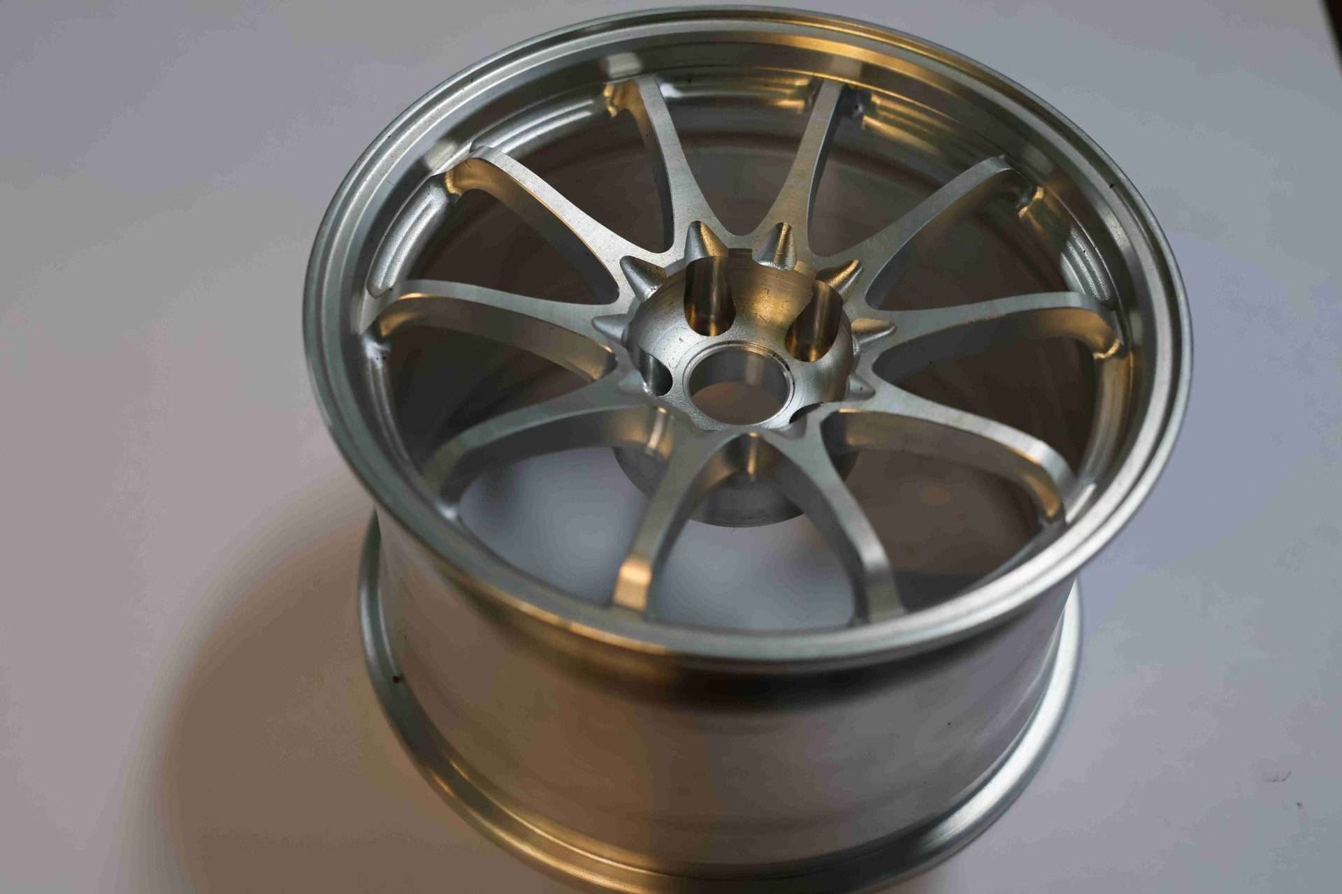
CNC part geometry optimization is the process of adjusting a part’s shape, features, and dimensions—wall thickness, corner radii, hole depths, tolerances—so it can be machined efficiently on CNC equipment without sacrificing function. It matters because geometry directly drives cycle time, tool wear, scrap rate, and fixturing complexity: a design that ignores tool access or unsupported walls forces slower feeds, more setups, or custom tooling. Optimizing geometry early, before parts reach the machine shop, shortens lead times and keeps per-part cost predictable across prototype and production runs alike.
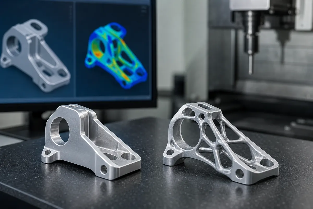
What Is CNC Part Geometry Optimization and Why Does It Matter?
CNC part geometry optimization means designing every feature around tool access, cutter geometry, and machine kinematics instead of fixing shape problems after the fact.
Treated correctly, geometry optimization happens on the CAD screen, not on the shop floor. Engineers check whether a cavity depth matches available tool lengths, whether a corner radius matches a standard end mill diameter, and whether a hole depth-to-diameter ratio stays within what a rigid tool can hold without deflecting. Treated as an afterthought, these same decisions surface as machine stoppages, tool breakage, or parts that fail inspection.
How Does Geometry Optimization Impact Machining Time and Production Costs?
Geometry decisions set cycle time by forcing tool size, feed rate, and pass count long before the spindle ever turns.
A deep cavity with a tight internal corner radius rules out a large-diameter cutter. That pushes the job toward a smaller tool, which must run at reduced feeds and speeds to avoid breaking, and often needs multiple roughing and finishing passes to clear the same volume a larger tool would remove in one pass. Tolerances multiply this effect. A tighter-than-necessary tolerance on a non-critical dimension can trigger a secondary grinding or lapping operation, additional CMM inspection time, and in some cases full rework if the first pass drifts outside spec, all of which add cost per part without adding function.
What’s the Difference Between Optimization Strategies for 3-Axis, 5-Axis, and Multi-Spindle CNC Machines?
Each machine architecture rewards a different geometry approach, so optimization has to match the equipment the part will actually run on.
A 3-axis mill needs flat-bottomed pockets and features accessible from a single orientation, or the part requires added setups. A 5-axis machine can reach compound angles in one clamping, which lets designers use organic contours and undercuts that a 3-axis process would need multiple fixtures to produce. Multi-spindle and Swiss lathe platforms favor rotationally symmetric geometry with features sized to standard tooling, since each unique feature adds a tool station and setup time. Unmanaged complexity across any of these platforms also fragments procurement: more unique tools, custom fixtures, and setup sheets mean more scheduling variables and more chances for a delay. MFG SOLUTION addresses this by matching part geometry to the most economical of five production methods, CNC turning, Swiss lathe, cold forging, automatic lathe, or CNC mill & turn, before quoting, which keeps tooling and setup decisions from becoming a bottleneck.
What Are the Key Design Principles for Optimizing CNC Part Geometry?
CNC part geometry optimization rests on four rules: adequate wall thickness, matched corner radii, sensible cavity proportions, and avoiding features that fight the cutting tool.
How Should You Design Wall Thickness, Corner Radii, and Internal Cavities for Optimal Machining?
Wall thickness should scale with both material and part height, not sit at one fixed number. As a general starting point, metal walls under roughly 0.8mm and plastic walls under 1.5mm start to flex under cutting pressure, causing chatter, dimensional drift, and in the worst cases, a snapped feature mid-cut. Taller, thinner walls need proportionally more thickness because unsupported length amplifies deflection the same way a longer diving board bends more than a short one.
Corner radii matter just as much. Internal corners should match a standard cutter radius, 3mm, 5mm, 6mm, rather than an arbitrary value that forces a custom tool or extra electrical discharge machining pass. Sharp 90-degree internal corners also concentrate stress in the finished part, which shortens fatigue life in load-bearing components.
Internal cavities need a depth-to-width ratio kept close to 4:1 or lower for standard end mills. Deeper, narrower pockets need long-reach or specialized tooling that flexes more, cuts slower, and costs more per part. Adding a few degrees of draft to cavity walls, where the design allows it, reduces tool deflection and improves surface finish on the pocket sides.
What Are the Most Common Design Mistakes That Lead to Manufacturability Issues?
Three mistakes show up repeatedly in part reviews. Sharp internal corners with zero radius force either a custom tool or a slower, multi-pass strategy that adds cost without adding function. Tolerances tighter than ±0.01mm on cosmetic or non-mating surfaces add inspection time and scrap risk for no functional benefit. Geometry that mixes deep pockets, odd hole angles, and thread types on a single part forces excessive tool changes, which stretches cycle time and raises the chance of setup error.
At MFG SOLUTION, engineering review during the 8-hour quoting process flags these issues before a part enters production, so the manufacturing method, CNC turning, Swiss lathe, or mill-turn, gets matched to the geometry rather than forced to accommodate it. For more information, see Cre Partners.
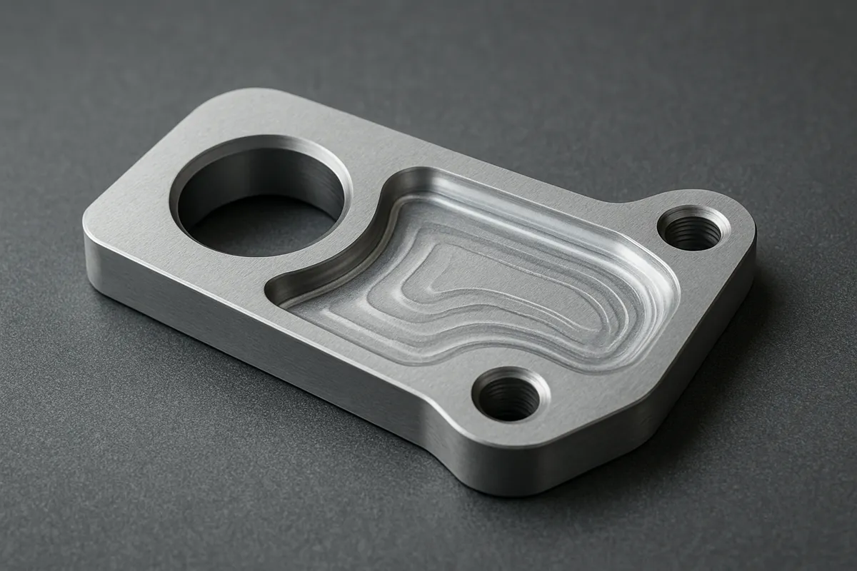
How Do You Balance Complexity, Tolerances, and Manufacturability in CNC Design?
CNC part geometry optimization means matching design ambition to shop-floor reality: pick machinable materials, hold tight tolerances only where function demands them, and plan workholding before you finalize a model.
What Material Selection Strategies Reduce Machining Difficulty and Improve Part Performance?
Material hardness and machinability rating directly set the achievable tolerance band, usable feed rate, and tool life on any given job. Free-machining brass or 6061 aluminum cuts fast, holds tight tolerances with less tool wear, and tolerates higher feed rates than hardened stainless or titanium, which demand slower speeds, more tool changes, and often a lower tolerance ceiling before cost climbs.
Choosing a softer, more machinable alloy where the application allows it can cut cycle time and tool costs without sacrificing part performance. When a harder material is required for strength, corrosion resistance, or a medical-grade spec, budget for slower cycles and expect tighter process control to hold the same dimensional targets.
How Do You Manage Overhangs, Undercuts, and Workholding Challenges in Complex Part Designs?
Overhangs and undercuts force extra setups, custom fixtures, or 5-axis repositioning, and each of those adds cost and lead time before the first chip flies. A pocket with an internal undercut that a standard 3-axis mill cannot reach usually means a second operation, a specialty tool, or a redesign, all of which push the part further from a fast turnaround.
Workholding needs to be part of the design conversation, not an afterthought discovered on the shop floor. Thin walls clamped in a standard vise can distort under cutting force, and a part designed without a flat reference surface may need a soft jaw or custom fixture just to sit still during machining. Building in a stable clamping surface early avoids redesign cycles later.
Tolerances follow the same logic: reserve tight tolerances for mating surfaces, bores, and functional interfaces, and leave everything else at standard shop tolerance. Over-specifying every dimension inflates inspection time and rejects parts that would otherwise pass. MFG SOLUTION’s 60+ engineering professionals review incoming specs against its five production methods, CNC turning, Swiss lathe, cold forging, automatic lathe, and CNC mill & turn, to flag geometry that would slow down an 8-hour quote or a 3-day ship window, before it reaches the machine.
What Software Tools and CAM Programs Help Automate CNC Part Geometry Optimization?
CAM simulation software, DFM checkers built into CAD platforms, and emerging AI-based analysis tools each catch a different class of geometry problem before a part reaches the shop floor.
CAM simulation runs the full toolpath against a virtual stock model, flagging tool-access gaps, spindle-to-fixture collisions, and unreachable pockets before a single chip gets cut. Catching these issues on screen instead of on the machine avoids scrapped setups, broken tooling, and the wasted material cost of a bad first article. Most shops treat this simulation pass as a gate, no program reaches the machine tool without clearing it.
How Do Fusion 360, Mastercam, and SolidCAM Compare for Geometry Optimization Workflows?
Integrated CAD/CAM environments keep geometry edits and toolpath feedback in one file, so a designer sees machinability warnings the moment a feature changes. Standalone CAM programs typically import a finished model from a separate CAD system, which is often more powerful for complex surfacing but adds a round trip every time geometry needs revision. For teams iterating quickly on part features, the tighter feedback loop of an integrated environment usually shortens design cycles; for shops running highly specialized toolpaths on locked-down geometry, a dedicated standalone CAM package can offer deeper control.
Are There AI or Machine Learning Tools That Can Automatically Analyze and Optimize Part Geometry?
A newer category of software scores a model’s machinability and suggests specific feature changes, flagging thin walls, undersized internal radii, or excessively deep pockets automatically during the design phase. These tools are assistive, not autonomous: they surface patterns from large geometry datasets, but final judgment on tolerance stack-up, fixturing, and material behavior still belongs to an engineer. At MFG SOLUTION, this kind of automated screening supplements, not replaces, the manual design-for-manufacturability review that 60+ engineering staff perform before quoting.
How Do You Troubleshoot and Avoid Common Geometry-Related Machining Failures?
Most chatter, tool breakage, and finish defects trace back to a specific geometric feature, not the feeds and speeds programmed around it.
What Causes Chatter, Tool Breakage, and Surface Finish Issues, and How Does Geometry Contribute?
Chatter usually appears when a thin wall flexes under cutting force or when tool stick-out is long relative to the depth of a feature. The cutter and the workpiece start vibrating against each other, and the marks show up as a rippled pattern on the surface. The fix rarely starts with slowing the spindle down, it starts with adding wall thickness, ribs, or support stock that gets removed in a later pass.
Tool breakage points to a different culprit: internal corners cut with a radius smaller than the cutter that has to machine them. A sharp-cornered pocket forces a small-diameter tool into a corner it cannot clear, and sudden changes in engagement, a tool going from light contact to full-width cut in one move, spike cutting forces and snap tools mid-cycle.
Surface finish problems often come from tool deflection in deep, narrow pockets, or from vibration transmitted through fixturing that is not rigid enough to hold the part still. Both trace back to geometry: pocket depth-to-width ratio in the first case, part shape and clamping surface in the second.
What Improvements Can You Expect from Geometry Optimization in Cycle Time and Cost per Part?
CNC part geometry optimization that addresses these root causes typically produces fewer setups, fewer tool changes, shorter cycle times, and lower scrap rates. None of that requires new equipment, it requires resizing corners, thickening walls, or rethinking a fixture.
Troubleshoot in sequence: identify the failure type, trace it to the feature causing it, then adjust radius, wall thickness, or fixturing before touching feeds and speeds. MFG SOLUTION’s engineering team applies this sequence during quote review, flagging geometry risks before a part reaches the shop floor.
Frequently Asked Questions
What is the difference between design for manufacturability (DFM) and geometry optimization?
DFM is the broad discipline of designing parts that can be produced reliably and affordably; geometry optimization is one specific tool within it. DFM also covers material selection, tolerancing strategy, and process choice. Geometry optimization narrows the focus to feature shapes: wall thickness, corner radii, pocket depth, hole placement, the physical dimensions a cutting tool has to navigate.
How early in the design process should CNC geometry optimization begin?
Start geometry review at the first CAD draft, before tolerances or finishes are finalized. Changing a wall thickness or internal corner radius costs nothing on screen but can force a full retool once a fixture or cutter path is already committed.
Does 5-axis machining eliminate the need to optimize part geometry?
No, 5-axis machines reduce some constraints but don’t remove the need for geometry optimization. They can reach angled and undercut features in fewer setups, but tool deflection, wall thickness limits, and internal corner radii still govern cycle time and part quality regardless of axis count.
Can geometry optimization reduce tooling and fixturing costs?
Yes, standardizing hole sizes, radii, and thread callouts across a part often cuts the number of unique tools a shop needs to stage. Fewer tool changes and simpler workholding also shorten setup time, which lowers per-part cost on batch runs.
What file formats work best for CAM-based manufacturability analysis?
Native CAD formats or STEP files (AP214/AP242) give CAM software the most accurate geometry for manufacturability checks. STL files, being faceted, lose precision on curved surfaces and small radii, which can hide problems that only surface once the tool path is generated.
Conclusion
Geometry optimization pays off in three concrete ways: fewer setups, less tool wear, and tighter cycle times, all decided before the first chip is cut. Prioritize wall thickness, corner radii, and hole standardization first, since these drive the majority of avoidable rework. Treat 5-axis capability as a complement to good geometry, not a substitute for it.
Next step: pull your current part drawing, flag every internal corner radius under 1mm and every wall thinner than 0.8mm, and send those flagged dimensions to a machinist for a manufacturability check before you release the file for quoting.
Recommended Articles
Explore more from our content library: