
2026-07-06
CNC Workholding Fixtures: Types, Tips & Best Practices
| Key Insight | Explanation |
|---|---|
| Fixtures hold parts, not just clamp them | A proper workholding fixture locates, supports, and clamps a part in a precise, repeatable position — all three functions must work together for accurate machining. |
| Wrong fixture = scrap parts | Poor workholding is one of the leading causes of dimensional errors and scrapped batches in precision CNC work, especially for tight-tolerance small parts. |
| Fixture type depends on part geometry and volume | Vises suit prismatic parts; collets and chucks handle round stock; custom fixtures are justified for complex geometries or high-volume production runs. |
| 3-2-1 locating principle is the foundation | Six degrees of freedom must be constrained to position a part repeatably. The 3-2-1 method uses three points on the primary datum, two on secondary, one on tertiary. |
| Fixture design affects tolerance stackup | Locating errors in the fixture compound with machining tolerances. Good fixture design minimizes stackup and keeps final part dimensions within spec. |
| Modular systems cut setup time significantly | Modular and quick-change workholding systems can reduce setup time by 50–70% compared to dedicated fixtures, improving throughput on mixed-production runs. |
CNC workholding fixtures are specialized devices that locate, support, and clamp a workpiece in a precise, repeatable position so a CNC machine can cut it accurately and safely. They’re the physical interface between your part and the machine table — and they determine whether a finished component meets tolerance or ends up in the scrap bin. This article covers every major fixture type, the engineering principles behind them, the mistakes that cost shops money, and the best practices that separate high-precision producers from the rest.
What Are CNC Workholding Fixtures?
CNC workholding fixtures are purpose-built devices that constrain a part’s position and orientation during machining, ensuring every cut is made at the correct location relative to the part’s datum. Without them, even a perfectly programmed toolpath produces inaccurate parts.
Definition and Core Functions
The term “workholding” covers the entire system that keeps a part stationary under cutting forces. A fixture specifically orients and locates the part — distinguishing it from a simple clamp, which only restrains movement. According to Purdue University’s manufacturing resources, workholding is fundamental to CNC mills and lathes because parts don’t exist in free space; something must grab and position them precisely before any cutting begins.
Every effective fixture performs three functions:
- Location: Positions the part against defined datum surfaces so the machine’s coordinate system aligns with the part’s geometry.
- Support: Prevents deflection under cutting forces, especially critical for thin-walled or long, slender parts.
- Clamping: Holds the part against locating surfaces without distorting it during the machining operation.
Why Fixtures Matter for Precision Manufacturing
In precision machining, tolerances of ±0.01mm or tighter are routine. Any movement during cutting — even a few microns — translates directly into dimensional error. Industry analysts consistently note that fixture-related errors account for a disproportionate share of non-conforming parts in high-mix, low-to-medium volume production environments.
Fixtures also affect cycle time. A well-designed fixture loads and unloads quickly, reducing non-cutting time. For high-volume runs, that adds up fast. Our related guide on machining tolerances explained covers how fixture-induced errors interact with overall part tolerance budgets — worth reading alongside this article.
Pro Tip: Always define your datum surfaces before designing a fixture. The fixture must reference the same datums called out on your engineering drawing — otherwise you’re building precision into the wrong reference frame entirely.
Types of CNC Workholding Fixtures
The right fixture type depends on part geometry, production volume, and the machining operation being performed. Choosing the wrong type is one of the most common — and costly — mistakes in CNC setup.
Standard Fixture Types
Most CNC shops work with a core set of fixture types that cover the majority of part geometries:
- Machine vises: The most common fixture for prismatic (block-shaped) parts on CNC mills. A precision vise clamps the part between a fixed and movable jaw. Suitable for short-run and prototype work due to fast setup.
- Collet chucks: Used on CNC lathes and Swiss lathe machines to grip round bar stock concentrically. Collets provide excellent repeatability and are ideal for small-diameter parts. At MFG SOLUTION, collet-based workholding is standard on our Swiss lathe operations for parts up to 38mm diameter.
- Three-jaw and four-jaw chucks: Three-jaw chucks self-center round parts quickly; four-jaw chucks allow independent adjustment for non-round or eccentric features. Advanced Manufacturing.org notes that hydraulic collet chucks and pullback chucks are increasingly common in automated production cells.
- Fixture plates and tooling plates: Flat plates with a grid of precision-tapped holes or T-slots. Parts or sub-fixtures bolt directly to the plate. Excellent for multi-part setups and pallet systems.
- Custom (dedicated) fixtures: Engineered specifically for a single part number. Higher upfront cost, but they deliver the fastest cycle times and tightest repeatability for high-volume production.
- Modular fixtures: Assembled from standardized components (blocks, risers, clamps, locating pins) on a base plate. Flexible, reusable, and well-suited to prototype and medium-volume work.
- Vacuum fixtures: Use negative pressure to hold flat, thin, or delicate parts without mechanical clamping forces that could distort the workpiece. Common in aerospace and electronics machining.
- Magnetic fixtures: Electromagnetic or permanent-magnet chucks hold ferrous parts on a flat surface. Fast to load and unload, with no clamping hardware obstructing the cutting tool.
Fixture Type Comparison Table
| Fixture Type | Best For | Setup Speed | Repeatability | Cost |
|---|---|---|---|---|
| Machine Vise | Prismatic parts, prototypes | Fast | Good | Low |
| Collet Chuck | Round bar stock, turning | Very Fast | Excellent | Low–Medium |
| Custom Fixture | High-volume, complex parts | Very Fast (once built) | Excellent | High (upfront) |
| Modular Fixture | Mixed production, prototypes | Medium | Good–Very Good | Medium |
| Vacuum Fixture | Thin, flat, delicate parts | Fast | Good | Medium–High |
| Magnetic Chuck | Flat ferrous parts, grinding | Very Fast | Good | Medium |
How CNC Workholding Fixtures Work
CNC workholding fixtures work by constraining all six degrees of freedom (three translational, three rotational) of a part so that its position relative to the machine’s coordinate system is fully defined and repeatable across every cycle.
The 3-2-1 Locating Principle
The 3-2-1 locating principle (also called the six-point locating rule) is the engineering foundation for virtually all fixture design. It works like this:
- Primary datum (3 points): Three contact points on the largest, most stable face of the part. These constrain three degrees of freedom: vertical translation and two rotational axes.
- Secondary datum (2 points): Two contact points on a perpendicular face. These constrain two more degrees of freedom: one translational and one rotational.
- Tertiary datum (1 point): One contact point on the third perpendicular face. This constrains the final translational degree of freedom.
Once all six degrees of freedom are constrained, the part is fully located. Clamping forces are then applied to hold the part against these locating points — never to locate it. Confusing clamping with locating is a fundamental design error.
Fixture Design and Tolerance Stackup
Fixture accuracy directly feeds into precision tolerance stackup. Every locating point has a positional tolerance. Those tolerances combine with the part’s own dimensional variation to produce the final stackup at the critical feature. A poorly designed fixture can consume a significant portion of the part’s total tolerance budget before the spindle even starts.
In practice, fixture locating surfaces are typically held to tolerances one grade tighter than the part itself. If a part feature requires ±0.02mm, the fixture locating surfaces should be accurate to ±0.005mm or better.
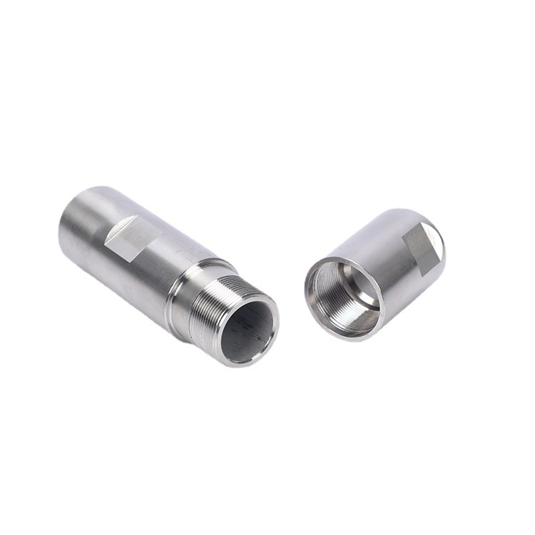
From experience, one of the trickiest scenarios involves thin-walled parts for medical device applications. A client producing stainless steel sleeve components needed a custom fixture that supported the part’s inner bore to prevent deflection during OD turning. Without that support, cutting forces caused the part wall to flex, producing out-of-round profiles that failed inspection. The fix was a mandrel-style fixture that expanded inside the bore — a classic support-before-clamp approach.
Pro Tip: Always apply clamping force directed toward the locating surface, not perpendicular to it. A clamp that pushes a part away from its datum contact points will shift the part every time it’s loaded, destroying repeatability.
Common Challenges and Mistakes
Even experienced machinists make workholding errors that result in scrapped parts, failed inspections, or damaged tooling. Knowing the most common pitfalls prevents expensive rework cycles.
The Most Costly Workholding Errors
- Over-clamping thin-walled parts: Applying too much clamping force distorts the part during machining. The part springs back to its original shape after unclamping, leaving features out of tolerance. This is especially problematic in CNC machining for medical devices and aerospace components where wall thicknesses are minimal.
- Locating on non-datum surfaces: Referencing the fixture off a rough or unmachined surface introduces positioning error. Always locate from finished datum surfaces called out on the drawing.
- Ignoring chip clearance: Chips packed under a part lift it off its locating surfaces. Fixture designs must include chip relief channels or air-blast ports to keep contact surfaces clean.
- Under-supporting long, slender parts: Parts with high length-to-diameter ratios deflect under cutting forces. For parts like long shafts and spindles, steady rests or follow rests are essential. This connects directly to the challenges discussed in our guide on CNC hole drilling technology, where drill wander on unsupported parts is a frequent issue.
- Skipping a repeatability check: Loading the same part 10 times and measuring its position each time (a gauge R&R on the fixture) is the only reliable way to verify fixture repeatability before committing to a production run.
- Using a fixture designed for one operation across multiple ops: A fixture optimized for Op 10 may not provide adequate access or support for Op 20. Each operation needs its own workholding analysis.
Challenges Specific to Small-Part Machining
Small parts (under 38mm diameter) present unique workholding challenges. Clamping forces that are trivial on a large part can easily distort a small one. Collet runout (the concentricity error between the collet bore and the spindle axis) matters enormously at small diameters — even 0.005mm of runout represents a significant fraction of the total tolerance on a 3mm part.
Industry experts note that Swiss lathe workholding, which uses a guide bushing to support the part immediately adjacent to the cutting zone, largely eliminates deflection issues for slender small parts. This is one reason Swiss lathe machining remains the preferred process for precision small-diameter components in medical and electronics applications.
Best Practices for CNC Fixture Design in 2026
The best CNC workholding fixture designs in 2026 combine proven mechanical principles with modern modular systems and simulation tools to reduce setup time, improve repeatability, and lower per-part costs.
Design Principles That Hold Up
- Start with the datum structure. Pull the datum reference frame directly from the engineering drawing. Your fixture must reference the same primary, secondary, and tertiary datums the designer specified — no improvisation.
- Apply the 3-2-1 rule rigorously. Six points, six degrees of freedom, no exceptions. Over-constraining (adding a fourth point to the primary datum, for example) causes indeterminate location and part distortion.
- Keep locating surfaces away from clamping forces. Clamps should push the part toward locators, not away from them or parallel to them.
- Design for chip evacuation from the start. Chip relief is not an afterthought. Plan channels, clearances, and air-blast ports during the initial fixture design phase.
- Use the lightest effective clamping force. Calculate the minimum clamping force needed to resist cutting forces, then add a safety factor of 1.5–2x. Don’t just tighten until it feels secure.
- Verify with simulation before cutting. Modern CAM software and fixture simulation tools can check for interference between the fixture, part, and cutting tool before the first chip flies.
Modular and Quick-Change Systems in 2026
As of 2026, modular workholding systems have become standard practice in high-mix precision shops. Systems built on standardized base plates with repeatable locating pins allow fixtures to be pre-set off the machine and swapped in minutes. Research from manufacturing engineering publications indicates setup time reductions of 50–70% compared to traditional dedicated fixtures on mixed-production runs.
At MFG SOLUTION, we’ve found that modular quick-change systems are particularly valuable for our 3-day ship commitment. Pre-setting fixtures offline means machine spindles stay cutting, not waiting for a setup technician to indicate a vise.
For 5-axis CNC machining, workholding design becomes even more critical. The fixture must provide full 5-sided access to the part while remaining rigid enough to withstand cutting forces from multiple directions. Trunnion-style fixtures and zero-point clamping systems are the current standard for 5-axis work, as documented by the 5-axis machining community’s ongoing analysis of workholding challenges.
Pro Tip: For high-volume production, calculate your fixture’s return on investment before committing to a custom design. Divide the per-part cycle time savings by the fixture cost. A fixture that saves 30 seconds per part on a 10,000-piece run pays for itself quickly — even at $2,000–$5,000 in tooling cost.
Fixture material selection also matters more than many engineers realize. Hardened steel inserts at locating contact points resist wear and maintain accuracy over millions of cycles. Aluminum fixture bodies reduce weight for manual handling but need steel wear pads at all contact surfaces. For the most demanding applications — such as CNC machining for medical devices under ISO 13485:2016 — fixture calibration records and maintenance logs are part of the quality system documentation.
Frequently Asked Questions
1. What is the difference between a fixture and a jig in CNC machining?
A fixture locates and holds a part in a fixed position relative to the machine — the cutting tool is guided by the machine’s CNC program. A jig, by contrast, physically guides the cutting tool (such as a drill bushing guiding a drill bit). In CNC machining, jigs are rare because the machine’s servo axes handle tool guidance; CNC workholding fixtures are far more common.
2. How do CNC workholding fixtures affect part tolerances?
Fixture locating errors add directly to the part’s tolerance stackup. If the fixture positions the part ±0.01mm from its nominal location, that error is present in every feature machined from that setup. Tight-tolerance parts require fixtures with locating accuracy significantly better than the part tolerance — typically by a factor of 3 to 5. Our article on precision tolerance stackup covers this relationship in more detail.
3. What materials are CNC workholding fixtures made from?
Common fixture materials include tool steel (hardened for wear resistance at contact surfaces), aluminum (lightweight for manual handling), cast iron (vibration damping for heavy cuts), and engineering plastics (for soft jaws that grip delicate parts without marring). High-volume production fixtures typically use hardened steel locating pins and bushings pressed into aluminum or steel bodies.
4. When should I invest in a custom fixture versus a modular system?
Custom fixtures make economic sense when production volumes are high enough to amortize the design and build cost over many parts — typically 1,000+ pieces per run. For lower volumes or prototype work, modular CNC workholding fixtures built from standardized components are more cost-effective. The break-even calculation depends on per-part cycle time savings versus fixture cost.
5. How do I prevent part distortion from over-clamping?
Calculate the minimum clamping force required to resist cutting forces, then apply a safety factor of 1.5–2x rather than tightening to feel. For thin-walled parts, use soft jaws, conforming fixtures, or internal mandrels that distribute clamping force over a larger area. Hydraulic and pneumatic clamping systems offer precise, repeatable force control that manual tightening can’t match.
6. Can CNC workholding fixtures be used for both milling and turning operations?
Generally, fixtures are operation-specific. Milling fixtures are stationary and designed for multi-axis cutter access. Turning fixtures (chucks, collets, face plates) rotate with the spindle and must be dynamically balanced. Some CNC mill-turn centers use specialized fixtures that work for both operations in a single setup, reducing part handling and improving datum consistency across features.
7. What role do workholding fixtures play in CNC threading operations?
Workholding is critical for threading because thread form accuracy depends on the part being held concentric and square to the threading tool or tap. Runout in the fixture or chuck translates directly into thread pitch diameter variation and form errors. For precision external and internal threads, collet chucks with minimal runout are preferred. See our guide on CNC threading services for more on how workholding affects thread quality.
8. How often should CNC workholding fixtures be inspected and recalibrated?
Inspection frequency depends on production volume and the fixture’s criticality to part quality. High-volume fixtures should be checked at the start of each production run using a reference part or gauge. Under ISO 9001:2015 and IATF 16949 quality systems, fixture calibration intervals must be documented and traceable. Locating surfaces should be inspected for wear whenever part measurements trend toward the tolerance boundary.
Conclusion
CNC workholding fixtures are the foundation of repeatable, high-precision machining. Get them right and your tolerances hold, your cycle times drop, and your scrap rate stays low. Get them wrong and no amount of programming skill or cutting tool quality will save the part.
The principles haven’t changed: locate before you clamp, reference the correct datums, constrain all six degrees of freedom, and design chip clearance in from the start. What has changed as of 2026 is the availability of modular quick-change systems, 5-axis compatible fixture designs, and simulation tools that let you verify fixture performance before cutting a single chip.
For small precision parts up to 38mm diameter, the stakes are even higher. Small features leave little room for fixture-induced error. That’s why MFG SOLUTION’s engineering team treats fixture design as a core competency, not an afterthought. Our ISO 9001:2015, ISO 13485:2016, and IATF 16949 certifications require documented, traceable workholding processes — and our 3-day ship window demands that those fixtures load and unload fast without sacrificing accuracy. If you’re sourcing precision small parts and want a partner who has the fixture engineering dialed in, request a quote and get a response within 8 hours.
Recommended Articles
Explore more from our content library: