
2026-10-28
CNC Machining for Industrial Electric Motor Components: End Covers, Bearing Seats, Shafts and Mounting Interfaces
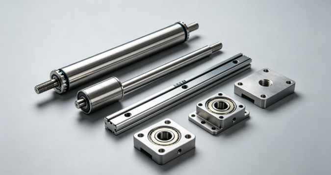

Industrial electric motors power pumps, conveyors, compressors, machine tools, packaging equipment, robotics and automated production lines. Their reliability depends not only on the electrical design but also on the precision of the mechanical components that support rotation, transmit torque, dissipate heat and connect the motor to surrounding equipment.
Motor housings, end covers, bearing seats, shafts, mounting flanges and adapter plates all have specific manufacturing requirements. A small deviation in a bearing bore or shaft interface can complicate assembly, while poorly controlled mounting surfaces may affect alignment with a gearbox, pump or driven machine.
CNC machining provides a flexible manufacturing method for custom electric motor components, especially when parts require accurately positioned holes, precision bores, threaded features, milled surfaces or complex interfaces. Depending on geometry and order volume, manufacturers may combine CNC milling, CNC turning, drilling, boring, reaming and secondary finishing operations.
For engineering teams and procurement professionals, the objective is not simply to machine every dimension as tightly as possible. It is to identify the features that determine fit and function, choose suitable materials, plan a stable manufacturing process and verify the finished components against the drawing.
MFG SOLUTION provides custom manufacturing through CNC machining services, CNC turning and complementary production processes. This guide explains how to manufacture industrial electric motor components with appropriate dimensional control, efficient process planning and consistent inspection.
1. Main CNC-Machined Components in Industrial Electric Motors
Different motor designs use different component configurations, but several mechanical parts commonly require precision manufacturing.
Motor housings and end covers
Motor housings support internal components and provide the external mounting structure. Depending on the design, they may include bearing seats, mounting feet, cooling features, threaded holes, cable-entry interfaces and machined locating surfaces.
End covers close the housing and frequently support bearings or establish the position of the rotating assembly. Their geometry must match the housing and bearing arrangement.
The manufacturing process may begin with a casting, billet or other suitable stock form. CNC machining then establishes the features that require controlled dimensions, flatness, hole position or surface finish.
Motor shafts
The shaft transmits torque from the rotor to the connected load. It may contain bearing journals, shoulders, keyways, threads, grooves, splines and coupling interfaces.
Because these features perform different functions, a shaft may require multiple operations. CNC turning establishes the principal cylindrical geometry, while milling or other processes create non-rotational features. Certain applications may also require grinding or heat treatment to meet specified mechanical and dimensional requirements.
Learn more about rotational components in the CNC turning parts guide.
Mounting flanges and adapter plates
Mounting flanges connect a motor to a gearbox, pump, machine frame or other equipment. Their hole patterns, locating diameters and mounting faces influence how accurately the motor fits into the assembly.
An adapter plate may also need to accommodate differences between two mounting standards. In these applications, the relationship between the bolt pattern and locating feature can be more important than the individual dimensions considered separately.
Bearing supports and precision spacers
Some motor assemblies use separate bearing supports, sleeves, spacers or locating rings. These parts establish axial or radial relationships between rotating and stationary components.
Their tolerances should be defined according to the bearing arrangement, operating conditions and assembly design rather than selected independently.
2. Material Selection for Motor Components
The correct material depends on the component’s structural function, operating environment, weight requirements, machinability and cost. Engineers should also consider thermal behavior, corrosion exposure and the compatibility of any surface treatment.
Aluminum alloys
Aluminum alloys are often considered for housings, end covers, adapter plates and lightweight structural components. They can be efficiently machined into pockets, mounting patterns, cable-entry features and other complex geometries.
However, not every aluminum grade provides the same strength or machinability. The alloy and temper should be selected according to the design requirements, and the manufacturing process should account for thin walls and possible distortion.
See the MFG SOLUTION guide to aluminum materials and machining for additional material-selection context.
Carbon and alloy steels
Steel is commonly considered for shafts and other components that require specific strength, toughness or wear properties. The selected grade and condition must match the mechanical requirements of the application.
If heat treatment is required, dimensional changes must be considered during process planning. The manufacturer may need to leave suitable finishing allowance for subsequent machining or grinding.
The 1045 steel turned parts guide provides further information about steel components and rotational manufacturing.
Stainless steel
Stainless steel may be suitable for motor components exposed to moisture, cleaning chemicals or corrosive environments, depending on the selected grade and service conditions.
Its machining behavior varies by grade. Work hardening, tool wear and surface quality may require careful process control, and stainless steel may not be necessary for components operating in ordinary protected environments.
For further reference, review the stainless steel machining guide.
Plastics and non-metallic components
Certain motor-related parts, such as spacers, insulation-related supports or custom covers, may use engineering plastics when the design permits. Material selection must consider temperature, dimensional stability, mechanical loading, electrical requirements and compatibility with the operating environment.
MFG SOLUTION’s material reference can help engineering teams compare material families before finalizing a specification.
3. Bearing Seats and Bore Accuracy
Bearing seats are among the most important mechanical features in many electric motor assemblies. Their dimensions and positions influence how the bearing is supported and how the rotating assembly aligns with the housing.
Specify the correct bearing fit
The appropriate fit depends on the bearing type, loading, housing or shaft material, temperature range and design arrangement. A generic bore tolerance should not be selected without considering the actual bearing specification.
Drawings should identify the required dimensions and tolerances for the shaft journal and housing bore, together with any geometric controls necessary for assembly.
Control bore position and alignment
Where two bearing supports establish the shaft axis, their relationship must be controlled according to the design. Incorrect positioning can create assembly difficulties and may affect the intended operating clearances.
A reliable manufacturing plan establishes datums and controls how the bearing features relate to the other functional surfaces.
Choose an appropriate machining process
Drilling may be adequate for preliminary holes, but precision bearing seats may require boring, reaming, fine finishing or another specified operation. The correct method depends on the required diameter, geometry, tolerance and surface condition.
For a deeper explanation, see the CNC hole tolerance guide.
Avoid unnecessary tolerance stacking
When multiple components are assembled, variation in each feature can accumulate. Engineers should identify the dimensions that directly control the shaft axis, bearing fit and mounting alignment.
Clear datum references and a suitable geometric dimensioning strategy can help reduce ambiguity between design, machining and inspection. The machining tolerances guide explains how to specify and control tolerances, while tolerance-related cost considerations help clarify the commercial impact of demanding requirements.
4. CNC Turning for Motor Shafts and Rotational Features
CNC turning is suitable for motor shafts, sleeves, spacers, locating rings and other components with rotational geometry.
A shaft drawing may include several diameters, bearing journals, shoulders, threads, grooves and coupling features. The manufacturing sequence must preserve the required relationships between these features.
Bearing journals and shoulders
Bearing journals require appropriate diameter and surface control. Shoulders may establish axial location or provide a seating surface for another component.
The drawing should specify the relevant dimensions and geometric requirements. Where the shaft has multiple critical diameters, the machining sequence should account for how the features relate to one another.
Keyways, splines and coupling features
Some motor shafts transfer torque through a keyway, spline, flat or other coupling interface. These features may be machined after turning, so workholding and datum selection must preserve their intended location and orientation.
If the shaft connects directly to a gearbox or pump, review the mating component’s interface requirements before manufacturing.
Surface finish and grinding
The required shaft finish depends on the function of each surface. Bearing journals, seal-running surfaces and ordinary clearance diameters may have different requirements.
Grinding may be appropriate where the specified dimensions, geometry or surface finish cannot be achieved economically through turning alone. It should be selected according to the drawing, material condition and production requirements rather than added automatically.
For small, slender shafts with many precision features, Swiss turning may be worth evaluating when the component geometry and order quantity justify the process.
5. Machining Motor Housings, End Covers and Flanges
Housings and end covers combine several feature types, often across multiple faces. A stable machining strategy must consider access, workholding, wall thickness and the relationship between functional surfaces.
Establish the datum scheme
Datums should reflect how the component is located in the final assembly. For example, a mounting face may provide the primary reference, while a locating bore or secondary face establishes orientation.
A consistent datum scheme helps keep bearing seats, mounting holes and other critical features related to the design intent.
Plan roughing and finishing operations
Roughing removes bulk material, while finishing establishes the final dimensions and surfaces. For some components, roughing before finishing can help manage material removal and distortion.
The appropriate sequence depends on the material, stock condition, geometry and tolerance requirements. Thin-wall components may require particular attention to clamping forces and material stability.
Select the right machine configuration
Three-axis CNC machining may be sufficient for accessible faces, pockets and holes. Four-axis or five-axis machining may help when features are distributed across multiple orientations or when setup reduction provides a meaningful advantage.
Five-axis machining should be chosen because the geometry and production plan justify it, not simply because it is a more advanced process. Review five-axis CNC machining capabilities when evaluating complex housing or adapter designs.
Use suitable workholding
Fixtures should locate the component repeatably while allowing access to the required features. Clamping must support the part without introducing unacceptable distortion.
For guidance on setup planning, see CNC workholding fixtures and best practices.
6. Mounting Interfaces, Hole Patterns and Alignment
Motor mounting features often connect multiple components within a larger mechanical system. The interface may include bolt holes, locating diameters, dowel holes, shoulders or machined contact faces.
Control bolt patterns
Hole position and spacing must match the mating component. When the bolt pattern is related to a locating bore or mounting face, the drawing should make that relationship clear.
Measuring individual hole diameters is not enough if the hole pattern itself controls assembly. Position tolerances or an appropriate inspection fixture may be necessary.
Maintain locating-face quality
A mounting face should meet the specified flatness and surface requirements. Burrs, damage or distortion may prevent the components from seating correctly.
Not every external face requires a fine finish. Requirements should focus on the interfaces that influence assembly, alignment or sealing.
Review the complete assembly
Where possible, provide the mating component drawing or assembly model during quotation. This helps the manufacturer understand which interfaces are critical and identify potential tolerance conflicts before machining starts.
Design teams can also use the principles in this CNC part geometry optimization guide to review wall thickness, corner radii, hole depths and tool accessibility.
7. Surface Finish, Deburring and Secondary Operations
Machined motor components may require deburring, polishing, grinding, coating or other finishing processes. These operations should be specified according to function and material.
Define surface requirements by function
Bearing seats, seal-running surfaces and mounting interfaces may need tighter surface controls than nonfunctional exterior faces.
A single surface-finish requirement applied to the entire component can increase cost without improving performance. Specify critical surfaces individually where necessary.
Account for finishing effects
Coatings and other treatments can affect dimensions, edge geometry and fit. Threads, bearing seats and locating diameters may need to be masked, finished afterward or otherwise accounted for in the process plan.
The treatment should be compatible with the material and intended environment. The CNC machining surface finish guide provides more detail on surface requirements and finishing decisions.
Remove burrs without damaging functional edges
Burrs around holes, slots and machined edges can interfere with assembly or handling. However, excessive edge breaking can also change a functional feature.
Drawings should define edge conditions where they matter. General notes should not override critical dimensions, sealing surfaces or specified sharp edges.
8. Quality Inspection for Industrial Motor Components
Inspection should verify that the finished part meets the drawing and purchasing specification. The inspection plan should prioritize the features that affect fit, alignment and function.
Dimensional inspection
Depending on the component, inspection may include:
- Bearing bore and shaft diameter
- Hole locations and mounting patterns
- Flatness and perpendicularity of mounting faces
- Thread dimensions and engagement
- Keyway or spline geometry
- Critical lengths and shoulder positions
- Surface finish on functional interfaces
Calipers and micrometers are suitable for some accessible dimensions. Bore gauges, thread gauges, height gauges, coordinate measuring machines or dedicated fixtures may be needed for more demanding features.
Material and process documentation
Where specified, material certificates and traceability records help establish that the supplied material matches the order. Heat treatment and surface treatment records may also be required.
The documentation should be agreed before production so that inspection, record preparation and delivery can be planned correctly.
First-article and repeat-production controls
For new designs or revised drawings, first-article inspection can verify whether the manufacturing route achieves the required features. Repeat production can then follow a defined inspection plan based on component risk, criticality and customer requirements.
MFG SOLUTION’s quality assurance standards guide and ISO 9001 precision machining guide provide further context on quality planning and manufacturing records.
9. Reducing Manufacturing Costs Without Compromising Function
The lowest machining quotation is not necessarily the lowest total cost. Setups, tooling, material waste, finishing, inspection and rework all influence the final price.
Apply tolerances where they matter
Identify the features that control bearing fit, shaft alignment and mounting interfaces. Apply appropriate general tolerances to noncritical dimensions where the design allows.
Tight tolerances can require slower machining, specialized tools, additional inspection and more demanding process control. They should be specified because the function requires them, not by default.
Simplify the design where possible
Accessible tool paths, sensible wall thicknesses, practical corner radii and clear datum references can make parts easier to manufacture.
Design changes must preserve the required mechanical performance. A manufacturability review should identify unnecessary complexity rather than remove features that are essential to the motor assembly.
Choose the production route according to volume
CNC machining is useful for prototypes, customized components and repeat batches requiring controlled interfaces. For larger volumes, casting or other near-net-shape processes followed by machining may be worth evaluating when the geometry and economics justify tooling investment.
MFG SOLUTION offers complementary manufacturing capabilities that can be assessed according to component geometry, material, tolerance and quantity.
Consider the full production cost
A meaningful cost comparison includes raw material, setup, cycle time, secondary operations, inspection, packaging and expected order volume. Review the CNC machining cost analysis guide when preparing a sourcing strategy.
10. What to Include in an RFQ for Motor Components
A complete request for quotation helps the manufacturer evaluate the component, choose a suitable production route and identify inspection requirements.
Include the following information where applicable:
- Current 2D drawing and matching 3D CAD model
- Material grade and required condition
- Order quantity and anticipated repeat volume
- Critical dimensions, datums and geometric tolerances
- Bearing fit and shaft interface requirements
- Mounting patterns and mating-component details
- Surface finish, heat treatment and coating requirements
- Thread specifications and edge conditions
- Inspection reports, certificates and traceability requirements
- Packaging and delivery expectations
Identify the drawing revision clearly. If the 2D drawing and 3D model conflict, resolve the discrepancy before production rather than assuming which document takes priority.
For custom components, provide any relevant assembly information that helps explain how the part functions. This can improve the engineering review and reduce ambiguity during quotation.
MFG SOLUTION supports custom precision manufacturing from prototype development to repeat production. Submit drawings through the online quote service or contact the team through the MFG SOLUTION contact page.
Frequently Asked Questions
1. Which electric motor components can be CNC machined?
Common examples include motor shafts, end covers, bearing supports, mounting flanges, adapter plates, spacers and custom housings. The appropriate process depends on geometry, material, tolerances and production quantity.
2. Which materials are suitable for motor housings and shafts?
Aluminum alloys may suit lightweight housings and covers, while carbon or alloy steels are often considered for shafts requiring specific mechanical properties. Stainless steel may suit selected corrosion-sensitive applications. The final choice depends on the design and operating conditions.
3. Why are bearing seats important?
Bearing seats establish the fit and support of the bearing assembly. Their dimensions, geometry and relationship to other features influence how the shaft is located and supported. Requirements should follow the bearing specification and mechanical design.
4. Does every motor shaft require grinding?
No. Grinding is appropriate when required dimensions, geometry or surface finish cannot be achieved economically through turning alone. The need depends on the drawing, material condition and application.
5. Can CNC machining produce custom motor mounting flanges?
Yes. CNC milling and drilling can produce mounting faces, hole patterns, locating features and other custom interfaces. The drawing should define the relationship between the mounting pattern and critical locating surfaces.
6. How should surface finish be specified?
Specify finish according to the function of each surface. Bearing seats, seal-running surfaces and mounting faces may need specific requirements, while ordinary exterior faces may use a general finish note.
7. What quality documents can be requested?
Depending on the project, buyers may request dimensional inspection reports, material certificates, traceability records and documentation for specified heat treatment or finishing processes. Agree on the requirements before production.
8. What information is needed for a CNC machining quotation?
Provide the current drawings and CAD model, material specification, quantity, critical tolerances, interface details, finishing requirements and inspection expectations. Complete information helps the manufacturer assess manufacturability, process steps and cost.
Conclusion: Precision Starts With the Motor’s Functional Interfaces
Industrial electric motor components require coordinated control of bearing seats, shafts, mounting interfaces, sealing features and material properties. A successful manufacturing plan begins by identifying how each feature contributes to assembly and performance, then connects those requirements to the machining sequence, workholding strategy and inspection plan.
Clear drawings, practical tolerances and appropriate finishing operations can reduce manufacturing risk while supporting consistent assembly. For procurement teams, a complete RFQ makes quotations easier to evaluate and reduces the likelihood of unexpected requirements after production begins.
MFG SOLUTION supports custom CNC machining for industrial components, from prototype projects to repeat orders. To discuss motor shafts, end covers, bearing supports, mounting flanges or other precision parts, submit your drawings through the online quote service or contact the team via MFG SOLUTION.