
2026-09-22
Why CNC Machining Tolerance Drives Your Part Price

Understanding what is CNC machining tolerance is essential. CNC machining tolerance is the allowable range of variation between a part’s finished dimension and its specified nominal size on the drawing, for example, 0.500 in. ±0.002 in. means the finished feature can measure anywhere from 0.498 to 0.502 in. and still be acceptable. Tolerances matter because no machining process produces a perfectly exact dimension every time; tool wear, material behavior, heat, and vibration all introduce small variation. Standard shop tolerances (often around ±0.005 in.) work for most parts and keep cost and lead time down; tighter tolerances are reserved for mating or high-precision features because they demand slower cuts, more inspection, and sometimes secondary finishing.

What Is CNC Machining Tolerance and Why Does It Matter?
Answering what is CNC machining tolerance starts with a single idea: no dimension on a drawing is ever produced exactly, tolerance is the window of acceptable variation around it.
Take a shaft specified at 0.500 in. with a tolerance of ±0.002 in. That callout tells the machinist the part is acceptable anywhere between 0.498 in. and 0.502 in., nothing outside that range passes inspection, regardless of how close it comes. The nominal dimension (0.500 in.) is the target; the tolerance band is the built-in acknowledgment that hitting that target exactly, every time, isn’t physically realistic.
Why Is There Always Variation in Machined Parts, Even With Precision Equipment?
Variation exists because cutting metal is a physical process, not a digital one, and physical processes push back. As a cutting tool engages material, it deflects slightly under load, and that deflection changes depending on depth of cut, tool length, and material hardness. Spindle runout, the tiny wobble in a rotating spindle or tool, adds its own layer of inconsistency, usually just a few microns, but enough to matter on tight-tolerance features.
Heat compounds the problem. Cutting generates friction, and friction expands both the workpiece and the machine structure during the cut; as the part cools afterward, its dimensions shift again. Fixture repeatability plays a role too, a part that isn’t clamped identically from one cycle to the next won’t cut identically either. None of this means CNC machining is imprecise. It means every finished dimension is the sum of several small, physical variables, which is exactly why tolerance exists as a formal specification rather than an afterthought.
How Do Material Properties Affect Achievable Tolerances?
Material choice changes what tolerance is realistic before a single cut is made. Aluminum machines predictably, cuts with relatively low force, and holds tight tolerances well, which is a major reason it’s a default choice for precision components. Steel requires higher cutting forces and generates more heat, so holding the same tolerance often means slower feeds, more tool wear, and tighter thermal control during the cut. Plastics behave differently still, many are prone to warping or relaxing internal stress after machining, so a feature that measures in-tolerance right off the machine can drift out of spec hours later.
This is why tolerance functions as a communication tool, not just a spec line. A tolerance callout tells a machinist exactly how much variation is acceptable on a given feature, removing guesswork on the shop floor about which dimensions are critical and which have room to move. At MFG SOLUTION, that clarity is built into quoting: parts up to 38mm in diameter are evaluated against drawing tolerances before a quote is issued within 8 hours, so tolerance requirements are confirmed before machining begins, not discovered during inspection.
What Are Standard CNC Machining Tolerances, and How Tight Can You Go?
Most CNC shops hold a standard tolerance of about ±0.005 in. (0.13 mm) on general features, tightening to ±0.001–0.002 in. (0.025–0.05 mm) on fits and mating surfaces. Understanding what is CNC machining tolerance in practice starts with recognizing that a single part often carries more than one band, loose on non-functional dimensions, tight where components actually touch.
Is 0.01 Inch Considered a Tight Tolerance, and What About 0.005 Inch?
Neither counts as tight by shop standards, 0.01 in. is looser than most default machine capability, and 0.005 in. sits right at the standard production tolerance many shops quote as their baseline. Tight, in practical terms, starts once you push below that standard band toward ±0.001 in. or finer, where variation in tooling, thermal drift, and fixturing starts to matter more.
Going below roughly a few thousandths of an inch usually means adding secondary operations, grinding, honing, or lapping, rather than just slowing down the milling or turning pass. Milling and turning alone have practical accuracy limits; once a print calls for something finer, the part typically leaves the CNC machine for a finishing step before it meets spec. That shift adds setup time, handling, and inspection, which is why tolerance tightening is one of the biggest cost levers on a quote.
Achievable tightness also depends on what kind of feature you’re calling out. A reamed hole diameter can often hold tighter tolerance than a milled flatness callout on a large face, and threads follow their own class system (2A/2B, 3A/3B) rather than a simple plus-or-minus band. Treat each feature type on its own terms instead of assuming one tolerance number applies uniformly across a drawing.
What’s the Difference Between Bilateral and Unilateral Tolerances, and When Do You Use Each?
Bilateral tolerance allows variation in both directions from a nominal dimension (e.g., 10.00 mm ±0.05 mm), while unilateral tolerance allows variation in only one direction (10.00 mm +0.10/–0.00 mm).
Designers reach for bilateral tolerances on general dimensions where either a slightly larger or smaller part still functions fine, it’s the simpler, more common default. Unilateral tolerances come into play for fits: a shaft that must never exceed a maximum diameter, or a hole that must never fall below a minimum, where one direction of error is safe and the other isn’t. Specifying the right type, not just the right width, is part of answering what is CNC machining tolerance for a given feature, get the direction wrong and a part that measures “in tolerance” on paper can still fail to assemble.
MFG SOLUTION applies this feature-by-feature approach across CNC turning, Swiss lathe, and CNC mill & turn work on parts up to 38 mm in diameter, matching tolerance bands to what each surface actually needs rather than tightening the whole print by default.
How Do Tolerances Affect Your Part Cost, Lead Time, and Quality?
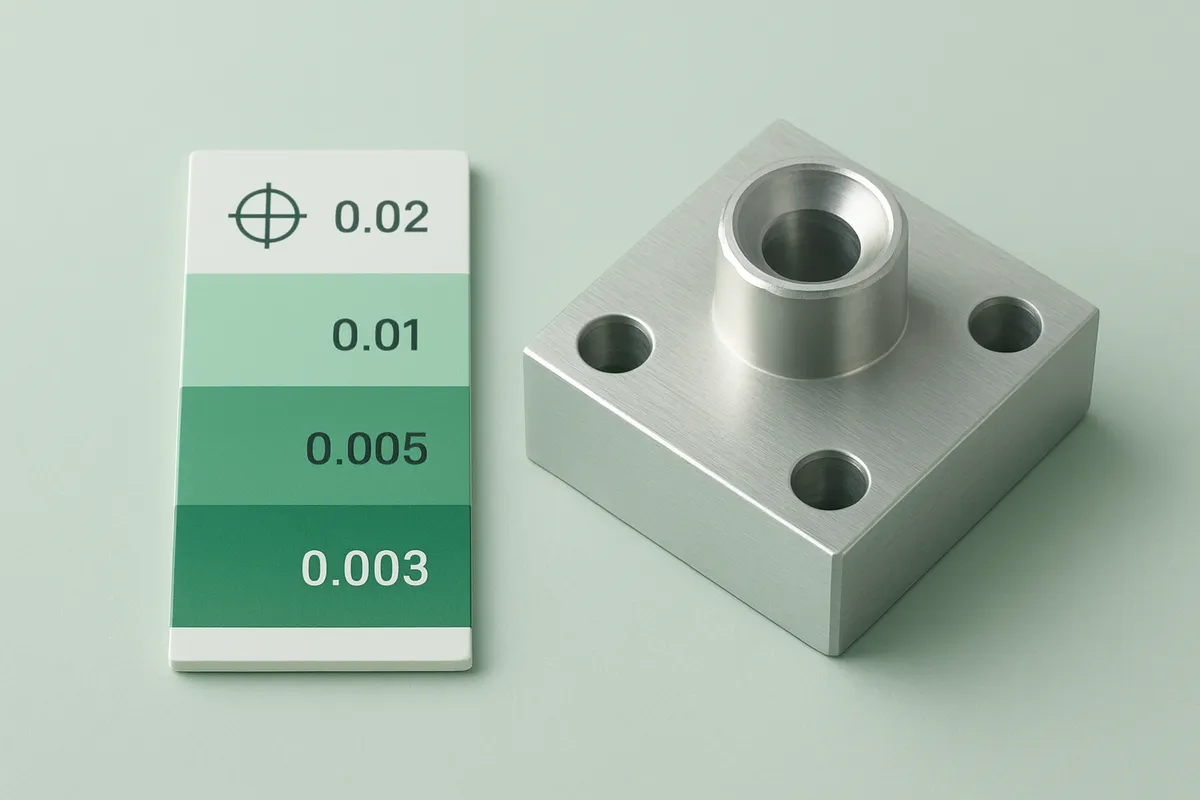
Tighter tolerances raise cost and lead time because they force slower cutting, more inspection, and higher scrap rates, while adding little value to features that do not need precision.
Understanding what is CNC machining tolerance in practice means tracing the mechanism from drawing callout to shop floor decision. A tolerance band is not just a number on a print, it dictates how a machinist runs the job.
Why Tight Tolerances Slow Down Production
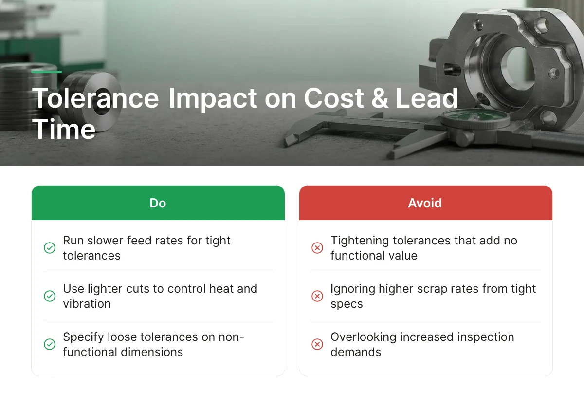
Holding a tight tolerance means running slower feed rates and lighter cuts to control heat and vibration, both of which distort dimensions if left unchecked. It also usually means more tool changes, since a worn tool drifts out of tolerance faster than it would for a looser callout, and more frequent in-process measurement to catch drift before it produces bad parts. Many tight-tolerance features also require secondary finishing, grinding, honing, or lapping, after the CNC operation, adding a separate step and separate handling time. Each of these adds machine time and labor, and that time is the primary driver of piece price.
How Scrap and Inspection Costs Compound
Tighter callouts push more parts toward the edge of the acceptable range, which raises scrap and rework rates compared to a standard shop tolerance. A part that fails a tight-tolerance check has already consumed machine time, material, and labor, so rework or scrap compounds cost rather than just adding it once. Inspection burden grows in step: tight tolerances typically require more CMM time per part and higher sampling frequency, sometimes full inspection instead of spot checks, which adds cost that never shows up in the cut time estimate alone.
When Should You Specify Tight Tolerances Versus Standard Tolerances?
Apply tight tolerance only to the features that control fit, function, or sealing, bearing bores, mating diameters, sealing surfaces, and leave every other dimension at standard shop tolerance. This feature-by-feature approach is the practical answer to what is CNC machining tolerance management: not a single number for the whole print, but a deliberate split between critical and non-critical dimensions. A drawing with one or two tight callouts and the rest at standard tolerance machines faster and inspects faster than one where every dimension carries the same tight band.
Is Tighter Tolerance Worth the Added Cost for Your Application?
Over-tolerancing an entire drawing does not make the part better, it adds cost without improving fit, function, or reliability on the features that do not need it. Cost scales with tolerance tightness in tiers rather than a straight line: budget-friendly tolerances suit non-critical dimensions, mid-range tolerances fit most functional features, and premium tolerances belong only on the surfaces where fit or sealing genuinely demands it. At MFG SOLUTION, engineers reviewing quotes within 8 hours flag which callouts are driving cost, so buyers can decide feature-by-feature whether the tighter spec earns its price before committing to a 3-day production run.
How Do You Read and Specify Tolerances on Engineering Drawings?
A toleranced dimension on a drawing shows three things: a nominal value, a plus/minus range or a reference to a general tolerance block, and sometimes a geometric symbol that controls shape or position rather than just size. Reading a drawing correctly means checking all three before assuming what a machinist will actually produce.
The nominal value is the target size, say, 10mm. Next to it, either a specific tolerance appears (10mm ±0.05mm) or nothing appears at all, which means the dimension falls back to whatever general tolerance is listed in the title block, often tied to a standard like ISO 2768. That title-block note is a default, not a decision, it applies automatically to every dimension the designer didn’t call out individually.
What Do GD&T Symbols Mean, and How Do You Interpret Them on a Drawing?
Geometric dimensioning and tolerancing (GD&T) symbols control shape, orientation, and location in ways a simple linear dimension cannot. Flatness restricts how much a surface can bow or warp, which matters when that surface needs to seal against another part. Perpendicularity controls the angle between two features, critical when a shaft must sit square to a mounting face. Position tolerances define how far a hole’s actual center can drift from its theoretical center, which is what determines whether a bolt pattern lines up. Concentricity controls how well two circular features share the same axis, important on rotating parts where imbalance causes vibration or wear.
Each of these symbols exists because a plus/minus dimension alone can’t describe form or relationship, a hole can be the right diameter and still be in the wrong place. Understanding what is CNC machining tolerance in this geometric sense, not just as a size window, is what separates a drawing that communicates intent from one that leaves it to guesswork.
What Real-World Failures Happen When Tolerances Are Specified Incorrectly?
Three patterns show up repeatedly. First, a missing datum reference, the drawing calls out a position tolerance but never establishes which surface or axis it’s measured from, so the machinist and the inspector measure from different points and get different answers. Second, a feature that actually controls fit gets left at the general tolerance because no one flagged it as critical, and the assembly doesn’t go together even though every dimension technically “passed.” Third, the drawing and the CAD model disagree, a revision updated one but not the other, and whoever is machining the part has to guess which one is authoritative.
Over-tolerancing causes its own damage: specifying tight tolerances on surfaces that don’t function critically can double machining time and raise inspection costs by roughly 40%, according to one precision-machining cost analysis. The fix is procedural, not just technical, involve the machinist or supplier before the design is finalized so they can flag which callouts are hard to hold and which general-tolerance defaults are actually risky for the part’s function. MFG SOLUTION’s engineering team reviews drawings during the 8-hour quoting window specifically to catch these conflicts before they reach the shop floor, where a datum ambiguity or a mismatched CAD file is far more expensive to resolve.
What Happens When Tolerances Stack Up, and How Do You Prevent Assembly Failures?
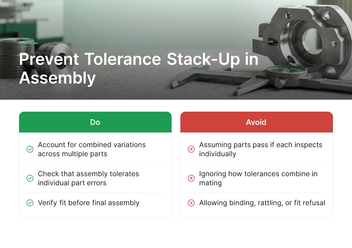
Tolerance stack-up occurs when the individual variations of multiple toleranced features or parts combine in an assembly, sometimes adding up to more error than the design can absorb. Each part might pass inspection on its own, yet the assembly still binds, rattles, or refuses to fit.
How Does Tolerance Stack-Up Affect Whether Parts Fit Together in Final Assembly?
Any answer to what is CNC machining tolerance has to account for what happens when tolerances combine, not just what a single part measures in isolation. A machined part rarely works alone, it mates with other parts, and each of those parts carries its own allowable variation. When a shaft, a bearing bore, a spacer, and a retaining clip all sit at the edge of their individual tolerance windows, the gaps or interferences between them can compound in one direction. The result is an assembly that fails to close, binds under load, or has more play than the design allows, even though every part on the bench passed its own drawing check.
What Are Practical Examples of Tolerance Stack-Up Causing Problems in Production?
Picture a four-part electronic housing: a base, a mid-plate, a bezel, and a cover, each held to a standard tolerance on its mating dimension. Individually, every part is within spec. Stacked together, if each part’s variation happens to land on the same side of its tolerance range, the total mismatch can exceed the clearance the design assumed, causing interference that prevents the cover from seating, or in the opposite direction, excessive play that lets the bezel rattle.
Engineers manage this risk two ways. Worst-case stack-up analysis assumes every part lands at its tolerance extreme simultaneously, the safest assumption, but often overly conservative for high part counts. Statistical stack-up analysis, commonly using root-sum-square (RSS) methods, assumes variations are randomly distributed and unlikely to all align in the worst direction, which better reflects real production data and permits looser tolerances on non-critical dimensions.
Practical Prevention Without Over-Tightening Everything
The fix isn’t tightening every dimension in the chain, that’s the expensive default, and it drives cost up sharply without addressing the real risk. Better practice is identifying the one or two dominant contributors to the stack and tightening only those, while choosing a datum scheme that references features consistently instead of chaining tolerances part to part, which compounds error unnecessarily. First-article inspection before a full production run catches stack-up problems while they’re still a one-part fix rather than a full-batch scrap event. MFG SOLUTION’s engineering team reviews stack-up risk during quoting, applying tighter tolerances only where they affect fit or function across the assembly.
Frequently Asked Questions
What is the most common tolerance used in CNC machining?
The general-purpose tolerance for most CNC-machined parts is around ±0.005 in. (0.13 mm), suitable for non-critical features.
Tighter tolerances near ±0.002 in. (0.051 mm) are used when mating parts or sealing surfaces require closer control. Reserve anything tighter for features that truly need it, since precision tolerancing raises machining time and inspection cost.
Can CNC machines hold tolerances tighter than a human hair?
Yes, a human hair is roughly 0.07 mm thick, and precision CNC equipment can hold tolerances well under that on select features.
Some processes achieve tolerances as tight as ±0.0005 in. (0.0127 mm) on specific dimensions, though holding that across an entire part is rarely practical or necessary.
Do all features on a drawing need the same tolerance?
No, applying one tight tolerance to every dimension wastes money on features that don’t affect fit or function.
Over-specifying tolerances on non-critical surfaces can double machining time and raise inspection costs by roughly 40%. Engineers should flag only the dimensions that control assembly, sealing, or performance, and leave the rest at standard shop tolerance.
How does part geometry affect which tolerance is achievable?
Thin walls, deep bores, and long unsupported features are harder to hold tight because they flex or deflect during cutting.
A CNC machine’s own accuracy is only part of the equation, variation in the same process, on the same machine, always produces small measurable differences between parts. Complex geometries with tight length-to-diameter ratios, interrupted cuts, or thin cross-sections typically need looser tolerances or specialized fixturing to hold accuracy consistently.
What inspection methods confirm a part meets its tolerance?
Common methods include calipers and micrometers for general dimensions, plus coordinate measuring machines (CMMs) for tight or complex tolerances.
Full process control, documented, auditable inspection at each production step, is what ISO 9001:2015 and IATF 16949 certification require, and it’s how manufacturers prove a batch of parts, not just one sample, meets print.
Conclusion
Tolerance is a cost lever, not just a spec. Match the tolerance to the function of each feature, mating surfaces and seals need tight control, cosmetic or non-critical dimensions don’t, and you avoid paying for precision you don’t need. Confirm early which manufacturing method fits your geometry and volume, since that decision affects both achievable tolerance and lead time.
Next step: pull your current drawing, mark which dimensions are truly functional, and submit it for a quote. MFG SOLUTION returns quotes within 8 hours and manufactures to ISO 9001:2015, ISO 13485:2016, and IATF 16949 standards for parts up to 38 mm in diameter.
Recommended Articles
Explore more from our content library: