
2026-05-18
CNC Part Finishing Techniques: A Complete Guide

| Key Insight | Explanation |
|---|---|
| Finishing affects function, not just looks | Surface finish directly impacts corrosion resistance, fatigue life, friction, and dimensional tolerances — not just aesthetics. |
| Ra 3.2 μm is the default | As-machined parts typically achieve Ra 3.2 μm (125 μin). Secondary finishing operations can reach Ra 0.4 μm or finer. |
| Technique selection depends on material and application | Aluminum, stainless steel, titanium, and plastics each respond differently to anodizing, electroplating, passivation, and polishing. |
| Cost scales with surface quality | Every step below Ra 1.6 μm adds cost. Specifying tighter finishes than required is one of the most common (and avoidable) cost drivers. |
| Certifications matter for regulated industries | Medical, automotive, and aerospace parts require finishing processes traceable under ISO 9001, ISO 13485, or IATF 16949 standards. |
| Post-machining finishing is a separate discipline | Roughing, semi-finishing, and finishing passes are distinct CNC stages — each with its own tooling, feeds, speeds, and quality checkpoints. |
Getting a part off the machine is only half the job. CNC part finishing techniques are the processes applied after primary machining to achieve the required surface quality, dimensional accuracy, corrosion resistance, and visual appearance. They span everything from a simple deburring pass to multi-stage electroplating and anodizing. Choose the wrong technique, and you’ll compromise part performance, fail a quality audit, or blow your unit cost. This guide covers every major method, how to select the right one for your material and application, and the pitfalls that trip up even experienced engineers.
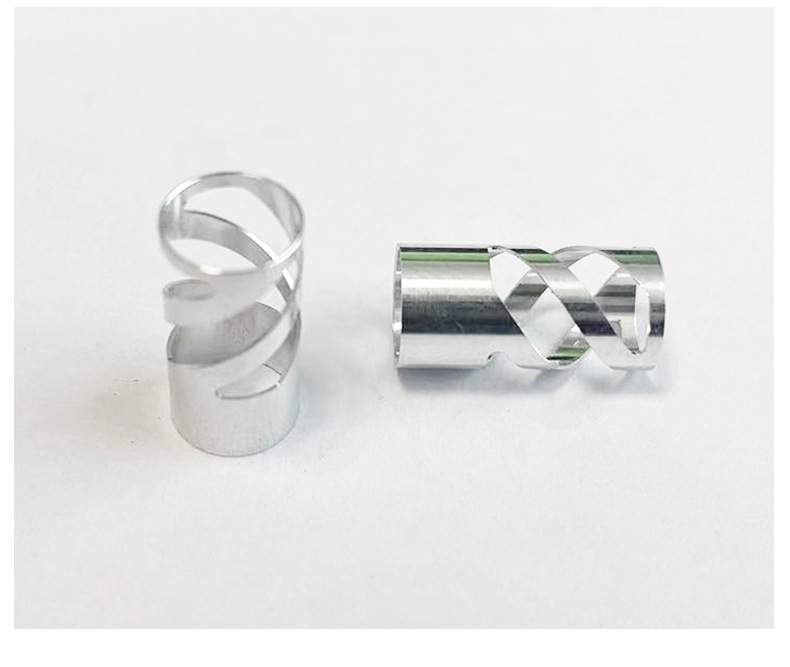
What Are CNC Part Finishing Techniques?
CNC part finishing techniques are the post-machining or in-process operations used to refine a part’s surface texture, geometry, and material properties beyond what the cutting tool alone can achieve. They include mechanical methods (polishing, grinding, bead blasting), chemical methods (passivation, chemical oxidation), electrochemical methods (anodizing, electroplating, electropolishing), and coating methods (powder coating, black oxide, PVD). The goal is always the same: match the part’s surface to its functional and regulatory requirements at the lowest practical cost.
Why Surface Finish Is a Functional Specification, Not an Afterthought
Surface roughness (Ra) is measured in micrometers (μm) or microinches (μin). Ra is the arithmetic average of surface profile deviations from a mean line. A lower Ra means a smoother surface. According to Hubs’ surface finish knowledge base, the standard as-machined Ra is 3.2 μm (125 μin), which suits most structural and non-sealing applications [1].
Surface finish affects:
- Fatigue resistance: Rough surfaces create stress concentrations that initiate cracks under cyclic loading.
- Corrosion resistance: Porous or rough surfaces trap moisture and contaminants, accelerating oxidation.
- Friction and wear: Mating surfaces in bearings, seals, and sliding contacts require controlled Ra values to function correctly.
- Dimensional tolerances: Coatings add material thickness; failing to account for this can push a part out of spec.
- Regulatory compliance: Medical device parts under ISO 13485 and automotive components under IATF 16949 require documented, traceable finishing processes.
The Ra Surface Finish Scale: A Quick Reference
| Ra Value (μm) | Ra Value (μin) | Typical Application | Common Process |
|---|---|---|---|
| 3.2 | 125 | Structural, non-sealing | As-machined |
| 1.6 | 63 | General mating surfaces | Finishing pass / light grinding |
| 0.8 | 32 | Sealing surfaces, bearings | Grinding, fine polishing |
| 0.4 | 16 | Precision hydraulics, optics | Lapping, honing, electropolishing |
| 0.1 or finer | 4 | Optical, medical implants | Super-finishing, diamond lapping |
How CNC Part Finishing Works: Stages and Processes
CNC finishing is a multi-stage workflow that begins during the machining cycle itself and continues through secondary post-processing operations. Understanding each stage helps you plan toolpaths, allocate time, and avoid rework.
The Three Machining Stages: Roughing, Semi-Finishing, and Finishing
According to a complete guide to CNC roughing and finishing, most precision parts go through three distinct cutting stages before any secondary finishing is applied [2]:
- Roughing: Removes the bulk of material as quickly as possible. Uses large-diameter tools, aggressive depth of cut, and high feed rates. Surface quality is deliberately sacrificed for speed. Ra values from roughing are typically 6.3–12.5 μm.
- Semi-finishing: Brings the part close to final dimensions, leaving 0.1–0.5 mm of material for the finishing pass. Reduces Ra to approximately 1.6–3.2 μm. Corrects any geometric errors introduced during roughing.
- Finishing: Uses smaller tools, lighter cuts, and optimized feeds/speeds to achieve the target Ra and dimensional tolerance. A well-executed finishing pass can achieve Ra 0.8 μm or better directly from the machine.
Only after these machining stages are complete do post-process finishing operations begin. Think of machining stages as the foundation; post-process finishing is the refinement layer.
Post-Process Finishing: Where Surface Quality Is Locked In
Post-process finishing operations fall into four broad categories:
- Mechanical finishing: Bead blasting, tumbling, vibratory finishing, grinding, lapping, honing, and polishing. These physically alter the surface profile.
- Chemical finishing: Passivation (for stainless steel), chemical oxidation (black oxide), and acid etching. These modify the surface chemistry without adding significant thickness.
- Electrochemical finishing: Anodizing, electroplating, electroless nickel plating, and electropolishing. These either deposit material onto the surface or remove it selectively using electrical current.
- Coating and painting: Powder coating, PVD (physical vapor deposition), and wet painting. These add a protective or decorative layer over the substrate.
Pro Tip: Always specify your finish requirement before machining begins, not after. Coatings like hard anodize (Type III) add 12–25 μm of thickness per surface. If you don’t account for this in your CAD model, your finished part will be out of tolerance.
Research from Scan2CAD’s analysis of CNC surface finishing strategies confirms that toolpath strategy during the finishing pass (plunge, zigzag, trochoidal, follow-part) has a measurable effect on Ra values, sometimes more so than feed rate alone [3].
Key CNC Part Finishing Techniques for 2026
The full range of CNC part finishing techniques spans mechanical, chemical, and electrochemical methods — each suited to specific materials, tolerances, and industry requirements. Here is a comprehensive breakdown of every major technique in use as of 2026.
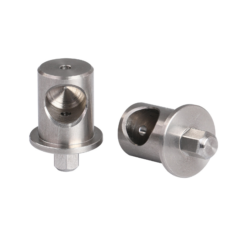
Mechanical Finishing Methods
- Bead blasting: Tiny glass beads are propelled at the surface under compressed air, creating a uniform matte or satin finish. It’s primarily used for cosmetic improvement and light deburring. Ra values typically fall between 1.6–3.2 μm. Per Hubs, bead blasting is one of the most popular post-process finishes for aluminum and stainless steel parts [1].
- Wet sanding: Uses progressively finer abrasive paper with a liquid lubricant to reduce Ra. Common for plastic and aluminum parts requiring a smooth, reflective finish without full polishing.
- Tumbling / vibratory finishing: Parts are placed in a drum or tub with abrasive media. The mechanical action deburrs edges and smooths surfaces uniformly. Excellent for high-volume small parts up to 38mm diameter.
- Grinding: Uses an abrasive wheel to achieve tight dimensional tolerances and Ra values as low as 0.4 μm. Cylindrical grinding is common for shafts and turned components.
- Lapping and honing: Ultra-fine abrasive processes for achieving Ra below 0.1 μm on precision bores, sealing surfaces, and hydraulic components.
- Polishing: Uses abrasive compounds and buffing wheels to achieve mirror-like surfaces. According to Techno FAQ’s surface finish guide, polishing is highly efficient for improving visual appearance but adds cost and time [4].
Chemical and Electrochemical Finishing Methods
- Passivation: A chemical process that removes free iron from stainless steel surfaces using nitric or citric acid, forming a passive chromium oxide layer that resists corrosion. Required for medical and food-contact components per ASTM A967.
- Black oxide: A chemical conversion coating that turns ferrous metals black, providing mild corrosion resistance and reduced light reflection. Adds virtually zero dimensional thickness.
- Anodizing (Type II): An electrochemical process that builds an aluminum oxide layer on aluminum alloys. Type II (sulfuric acid) produces a 5–25 μm layer. Improves corrosion resistance and allows dyeing for color.
- Hard anodizing (Type III): A thicker, harder version of anodizing (12–100 μm). Significantly increases surface hardness (up to 70 HRC equivalent) and wear resistance. Used in aerospace, hydraulics, and automotive applications.
- Electroplating: Deposits a metal layer (nickel, chrome, zinc, gold) onto the substrate using electrical current. Improves corrosion resistance, hardness, or conductivity depending on the plating metal.
- Electroless nickel plating: Deposits a uniform nickel-phosphorus layer without electrical current, making it ideal for complex geometries where uniform coating thickness is critical. Per HPPI’s surface finishing guide, electroless nickel provides excellent corrosion and wear resistance [5].
- Electropolishing: The reverse of electroplating. Selectively removes surface material at microscopic high points, reducing Ra and producing a bright, smooth finish. Common for medical implants and food-grade stainless steel.
- Chemical oxidation / Alodine (Chem film): A chromate conversion coating for aluminum that provides corrosion resistance and electrical conductivity. Adds less than 1 μm of thickness. Per Fictiv’s CNC finishing guide, chem film is widely used in aerospace and electronics [6].
Coating Methods
- Powder coating: Electrostatically applies dry polymer powder, then cures it in an oven. Produces a durable, thick (50–100 μm) decorative and protective finish. Works on steel, aluminum, and cast iron.
- PVD coating (Physical Vapor Deposition): Deposits ultra-thin (2–5 μm) hard coatings like TiN, TiAlN, or DLC in a vacuum chamber. Dramatically increases surface hardness and reduces friction. Common for cutting tools and precision wear components.
- Nanocoating and laser etching: Emerging techniques as of 2026. Colburn Manufacturing notes that nanocoatings and laser surface texturing are gaining traction in Swiss machining and CNC applications for parts requiring extreme precision and minimal coating thickness [7].
Pro Tip: For small parts under 38mm diameter — the kind produced on Swiss lathes and CNC turning centers — tumbling and vibratory finishing are often the most cost-effective mechanical finishing methods. They process hundreds of parts simultaneously with consistent results, keeping per-unit finishing cost low.
Common Challenges and Mistakes in CNC Finishing
The most costly finishing mistakes aren’t made at the finishing stage — they’re made during design and process planning, long before the part reaches a tumbler or an anodizing tank.
Over-Specifying Surface Finish
A common mistake is specifying Ra 0.4 μm (16 μin) on a drawing when Ra 1.6 μm (63 μin) would perform identically in service. According to DATRON’s surface finish guide, every step tighter than Ra 1.6 μm requires additional machining passes, specialized tooling, and stricter quality control — all of which add cost without adding functional value if the specification isn’t justified [8].
In practice, this over-specification problem is pervasive. Engineers default to tight tolerances out of habit, not necessity. A good rule: specify the finish your application actually needs, then verify it with a functional test, not an assumption.
Ignoring Coating Thickness in Dimensional Planning
One pitfall to watch for: failing to account for coating buildup. Hard anodize adds up to 50 μm per surface. Chrome plating can add 25–500 μm. If your part has a bore diameter of 10.000 mm with an H7 tolerance (+0.015/0.000 mm), a 25 μm hard anodize layer reduces the bore diameter by 50 μm total — pushing it 35 μm below the minimum acceptable dimension.
At MFG SOLUTION, we’ve found that the most effective approach is to machine parts to a pre-finish dimension that accounts for coating buildup, with the final coated dimension hitting the nominal tolerance. This requires close coordination between the machining team and the finishing supplier from day one.
Choosing the Wrong Finish for the Material
Not all finishes work on all materials. Common mismatches include:
- Anodizing applied to steel (it only works on aluminum, titanium, and a few other non-ferrous metals)
- Passivation applied to aluminum (passivation is for stainless steel; aluminum requires Alodine or anodizing)
- Powder coating applied to parts with tight internal threads (the thick coating layer fills threads, requiring masking or post-coating tapping)
- Electropolishing applied to low-alloy steels (it works best on austenitic stainless steel and some copper alloys)
Industry analysts suggest that material-finish compatibility reviews should be a mandatory step in design for manufacturability (DFM) checks. A DFM review early in the design cycle catches these mismatches before they become expensive rework.
Skipping Deburring Before Secondary Finishing
Deburring is not optional. Burrs left from machining will cause uneven coating adhesion, mask dimensional features, and create sharp edges that are safety hazards in assembly. BDE Manufacturing’s finishing guide emphasizes that deburring is the foundational step before any secondary finish is applied [9].
Best Practices for CNC Part Finishing in 2026
Effective CNC part finishing techniques require a systematic approach that integrates material knowledge, process sequencing, and quality verification at every stage.
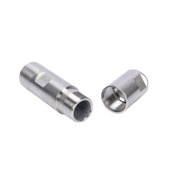
Match the Finishing Process to the Application, Not the Budget Alone
The cheapest finish isn’t always the best choice. Use this decision framework:
- Define the functional requirement: Does the part need corrosion resistance, wear resistance, electrical conductivity, biocompatibility, or purely cosmetic improvement?
- Identify the base material: Aluminum, stainless steel, titanium, brass, copper, and plastics each have compatible finishing processes. Confirm material-finish compatibility before specifying.
- Set the Ra target based on function: Use the Ra chart above. Don’t tighten Ra beyond what the application demands.
- Account for dimensional impact: Calculate pre-finish dimensions for all features that have tolerances, especially bores, shafts, and threaded features.
- Verify with a first-article inspection: Measure Ra, coating thickness, and critical dimensions on the first finished part before committing to a full production run.
Process Sequencing: Get the Order Right
Finishing operations must follow a logical sequence. Doing them out of order causes rework or scrapped parts.
- Deburr before any secondary finish
- Complete all heat treatment before grinding or precision finishing (heat treatment changes dimensions)
- Apply conversion coatings (passivation, Alodine) before any organic coatings (powder coat, paint)
- Mask threads, bores, and precision surfaces before coating operations
- Inspect Ra and dimensions after each stage, not just at the end
Pro Tip: For regulated industries (medical, automotive, aerospace), every finishing step must be documented and traceable. ISO 9001:2015 requires process records; ISO 13485:2016 adds biocompatibility and sterility considerations. Our team at MFG SOLUTION recommends building your finishing process documentation into the production router from day one — not as a retrofit after an audit finding.
Leverage the Right Machining Method to Minimize Finishing Costs
The best finishing strategy starts with the right machining method. Swiss lathe machining, for example, produces exceptionally consistent surface finishes on small-diameter parts (under 38mm) due to the guide bushing support that minimizes deflection. Parts machined on a Swiss lathe often require less secondary finishing than those produced on conventional CNC turning centers. Goodwin University’s overview of CNC machining techniques highlights how process selection upstream directly affects downstream quality requirements [10].
Similarly, 5-axis CNC milling can produce complex contoured surfaces in a single setup with consistent Ra values, reducing the number of secondary finishing operations needed. Choosing the right upstream process is the most cost-effective finishing strategy available.
| Finishing Technique | Best Material | Achievable Ra | Adds Thickness? | Relative Cost |
|---|---|---|---|---|
| Bead Blasting | Al, SS, Ti | 1.6–3.2 μm | No | Low |
| Tumbling | Most metals | 0.8–1.6 μm | No | Low |
| Anodize Type II | Aluminum | Similar to base | Yes (5–25 μm) | Low–Medium |
| Hard Anodize Type III | Aluminum | 0.8–1.6 μm | Yes (12–100 μm) | Medium |
| Electroless Nickel | Steel, Al | Mirrors base | Yes (5–125 μm) | Medium–High |
| Electropolishing | SS, Cu alloys | 0.1–0.4 μm | No (removes) | Medium–High |
| Passivation | Stainless Steel | No change | Negligible | Low |
| Powder Coating | Steel, Al | Variable | Yes (50–100 μm) | Low–Medium |
| PVD Coating | Most metals | Mirrors base | Yes (2–5 μm) | High |
Sources & References
- Hubs, “What are the types of surface finishes for CNC machining?”, 2026
- Casting China, “CNC Roughing and Finishing: A Complete Guide to Machining”, 2026
- Scan2CAD, “Achieving Superior Surface Finishes in CNC Machining”, 2026
- Techno FAQ, “9 Common Surface Finishes In Metal CNC Machining”, 2021
- HPPI, “Technical Guide: Surface Finishes | Precision CNC Machining”, 2026
- Fictiv, “Mastering the Art of Finishing CNC Machined Parts”, 2026
- Colburn Manufacturing, “Exploring Metal Finishing Techniques in CNC Machining”, 2026
- DATRON, “Achieve The Perfect CNC Machining Surface Finish”, 2026
- BDE Manufacturing, “Essential Guide to Surface Finishing for CNC Machined Parts”, 2026
- Goodwin University, “7 Essential CNC Machining Techniques”, 2026
- RapidDirect, “The Ultimate Guide to CNC Machining Surface Finish”, 2026
Frequently Asked Questions
1. What are the 5 types of metal finishing?
The five primary categories of metal finishing used in CNC part finishing techniques are: (1) mechanical finishing (polishing, grinding, bead blasting, tumbling), (2) chemical finishing (passivation, black oxide, chemical etching), (3) electrochemical finishing (anodizing, electroplating, electroless nickel, electropolishing), (4) conversion coatings (Alodine/chem film, chromate conversion), and (5) applied coatings (powder coating, PVD, wet paint). Each category serves distinct functional purposes — corrosion protection, hardness, conductivity, aesthetics, or dimensional refinement — and the right choice depends on your base material and application requirements. According to RapidDirect’s surface finish guide, selecting the wrong category for your material is the most common and costly finishing mistake [11].
2. What is the standard finish for machined parts?
The standard as-machined surface finish is Ra 3.2 μm (125 μin), which results from a typical CNC turning or milling operation without any secondary finishing. A dedicated finishing pass reduces Ra to 1.6 μm (63 μin); further grinding or polishing can achieve 0.8 μm (32 μin) or 0.4 μm (16 μin). Each step below Ra 1.6 μm increases part cost, cycle time, and quality control requirements — so you should only specify tighter finishes when the application genuinely demands it (sealing surfaces, bearing journals, medical implants). For most structural and non-sealing features, Ra 3.2 μm is both sufficient and cost-optimal.
3. What are the common mistakes made by machinists in CNC finishing?
The most impactful finishing mistakes go beyond setup errors. The top issues are: over-specifying Ra values that add cost without functional benefit; failing to account for coating thickness in dimensional planning (especially for anodizing and electroplating); skipping deburring before secondary finishing; choosing a finish incompatible with the base material; and neglecting to document and sequence finishing operations correctly for regulated industries. In practice, most finishing rework traces back to design decisions made before the first chip was cut — not to operator error on the shop floor. A thorough DFM review that explicitly addresses surface finish requirements prevents the majority of these problems.
4. What is the difference between anodizing Type II and Type III?
Type II anodizing (standard sulfuric acid anodize) produces a 5–25 μm aluminum oxide layer, providing good corrosion resistance and the ability to accept dyes for color. Type III (hard anodize) uses a lower temperature and higher current density to produce a 12–100 μm layer with significantly higher hardness (up to 70 HRC equivalent) and superior wear resistance. Type III adds more dimensional thickness and is harder to dye due to its dense structure. Use Type II for cosmetic and general-purpose corrosion protection; use Type III for wear surfaces, hydraulic components, and high-load sliding interfaces. Both are commonly specified in aerospace and automotive CNC part finishing techniques.
5. Can CNC part finishing techniques be applied to plastic parts?
Yes, though the options differ from metal. Plastics can be finished by wet sanding, bead blasting (with care to avoid melting), vapor polishing (for clear acrylics and polycarbonates), painting, and in some cases electroplating (after a conductive primer is applied). Vapor polishing uses solvent vapor to reflow the surface of compatible thermoplastics, achieving a clear, high-gloss finish without abrasion. Anodizing and passivation are metal-specific processes and don’t apply to plastics. For precision plastic parts, the as-machined finish is often sufficient, and the key finishing concern is deburring sharp edges without distorting fine features.
6. How do I specify surface finish on a technical drawing?
Surface finish is specified on engineering drawings using the Ra symbol (a triangle with an extension line) per ISO 1302 or ASME Y14.36M standards. You specify the Ra value in μm or μin, the sampling length, and any directional requirement (lay). For coatings, a separate finish callout or note block specifies the process (e.g., “Hard Anodize Type III per MIL-A-8625, Class 2, 25 μm min”), the applicable standard, and any masking requirements. Always include a general finish note for surfaces without individual callouts (e.g., “All unmachined surfaces: Ra 3.2 μm unless otherwise noted”). Consistent, complete finish callouts prevent ambiguity and supplier interpretation errors.
Conclusion
Selecting the right CNC part finishing techniques is as important as selecting the right machining process. The finish you specify determines corrosion resistance, wear life, dimensional accuracy, regulatory compliance, and unit cost. Get it right, and your parts perform in service without rework or field failures. Get it wrong, and you’ll spend more fixing the problem than the finishing operation itself would have cost.
The practical takeaway is straightforward: match your finish to your function, account for coating thickness in your dimensional stack-up, deburr before you coat, and document every step for traceability. These aren’t advanced concepts — they’re disciplined habits that separate reliable production from expensive rework cycles.
At MFG SOLUTION, we apply these principles across every part we produce. With ISO 9001:2015, ISO 13485:2016, and IATF 16949 certifications, 60+ engineering professionals, and production capabilities spanning CNC turning, Swiss lathe, 5-axis milling, and cold forging, we build finishing requirements into the process from the first quote. You get a detailed quote within 8 hours and your parts ship within 3 days — with full process documentation and quality traceability included. If you’re sourcing precision small parts up to 38mm diameter and need a manufacturing partner who treats surface finish as a functional specification, not an afterthought, we’re ready to help.
About the Author
Written by the Manufacturing – Precision Machining & CNC Services experts at MFG SOLUTION. Our team brings years of hands-on experience helping businesses with Manufacturing – Precision Machining & CNC Services, delivering practical guidance grounded in real-world results.
Recommended Articles
Explore more from our content library: