
2026-09-19
How to Prepare Drawings for Rapid Turnaround Machining

Understanding rapid turnaround machining services is essential. Drawings enable fast, cost-effective machining when they eliminate ambiguity: dimension only critical and measurable features, specify materials and tolerances that match the part’s actual function, and put quality requirements directly on the print instead of in separate documents. Every unclear call-out, over-tight tolerance, or missing hardware spec forces a manufacturer to stop and ask questions, and each round of clarification adds days to your turnaround. Clean, complete drawings let a shop quote and machine the part on the first pass.
What You’ll Need Before Formatting Drawings for Rapid Turnaround Machining Services
A complete package for rapid turnaround machining services has four parts: a dimensioned print, a 3D CAD model, a material specification, and any hardware or BOM references the part depends on. Gather all four before you touch a single dimension line.
Each piece does a different job, and a shop needs both the model and the drawing to quote accurately. The CAD model defines geometry, the exact shape, surfaces, and volumes a machinist’s CAM software will read to generate toolpaths. The drawing carries everything the model can’t show: tolerances, surface finish, thread callouts, and which features actually matter for the part to function. Send a model with no drawing and a machinist has to guess your intent. Send a drawing with no model and someone has to rebuild geometry by hand before quoting can even start.
- Dimensioned print: a 2D drawing with critical dimensions, tolerances, and finish callouts placed directly on the print
- 3D CAD model: native or neutral-format file (STEP, IGES) that defines exact part geometry
- Material specification: exact grade and condition, not just “aluminum,” but 6061-T6 or equivalent
- Hardware and BOM references: supplier and part number for any fasteners, inserts, or mating components
Skip any one of these and you create a gap the shop has to fill before work can begin. That gap becomes a clarification request, an email or call asking what you meant by an ambiguous dimension, an unspecified finish, or a missing thread class. Clarification cycles are the single biggest cause of delayed quotes, because every round-trip adds a day or more while your package sits in someone’s inbox waiting for an answer.
At MFG SOLUTION, a complete package is what makes an 8-hour quote and 3-day shipment possible, incomplete submissions are the exception that breaks that timeline.
The rest of this guide walks through the specific edits, dimensioning, tolerancing, material callouts, and finish notes, that turn a rough drawing into one a shop can quote and machine on the first pass.
Dimension Only Critical and Measurable Features
Tolerance only the dimensions that control fit, function, or assembly, everything else should default to standard shop tolerances your supplier already machines to.
Over-dimensioning happens when every feature on a drawing gets a tight tolerance, whether or not it affects how the part works. A drawing that calls out ±0.01mm on a cosmetic chamfer forces the machinist to treat that feature with the same caution as a load-bearing bore. That slows the whole job down, even though the chamfer’s actual dimension barely matters.
How Do I Consolidate Call-Outs and Avoid Over-Dimensioning?
Start by separating features into two buckets: those that mate, seal, press-fit, or bear load, and those that don’t. Mating surfaces, press-fit diameters, and sealing faces need explicit tolerances because a few microns of drift can cause an assembly failure or a leak. Cosmetic edges, non-functional radii, and appearance-only dimensions rarely need anything tighter than the shop’s standard tolerance band.
- List every dimension on the drawing and mark which ones interact with another part or a seal.
- Leave the rest to general tolerance notes rather than individual call-outs.
- When a feature repeats, a bolt pattern, a series of identical holes, a repeated slot, dimension it once and reference the count and spacing, instead of writing out the full dimension string for each instance.
Repeated full-length dimension strings for identical features are one of the more common drafting habits that create confusion rather than clarity. Consolidating those call-outs into a single, clearly labeled instruction does the same job with less clutter and less room for misreading.
How Does Over-Tolerancing Impact Cost and Lead Time?
Tight tolerances force slower cutting speeds, more frequent tool changes, and added inspection steps, all of which stack directly onto machine time and cost. A machinist working to a ±0.005mm callout can’t run the same feed rates as one working to a standard ±0.05mm tolerance, and each tight-tolerance feature usually needs its own inspection step to confirm it before the part ships.
Unclear or duplicated annotations are also a common reason manufacturers send back clarification requests before a job even starts, and every round of back-and-forth adds days to a quote that should take hours. That friction runs against the entire premise of rapid turnaround machining services, where speed depends on the shop reading a drawing once and moving straight to production.
At MFG SOLUTION, quotes turn around within 8 hours partly because clean, well-toleranced drawings let engineers assess feasibility and cost without a clarification cycle. Parts machined up to 38mm in diameter across CNC turning, Swiss lathe, and mill-turn processes move faster through review when the print states plainly what matters and leaves the rest to standard practice.
Specify Materials and Threaded Features to Support Fast Production
Material choice and thread call-outs change how fast a shop can cut, tap, and ship a part, often more than any other decision on the drawing. Pick a readily available alloy and standard thread specs, and rapid turnaround machining services can move your job straight to the machine instead of routing it through engineering for clarification.
Which Materials Machine Fastest and How Should I Specify Them?
Machinability depends on hardness, how the material forms chips during cutting, and how fast it wears down tooling, softer, free-machining alloys like 303 stainless or 6061 aluminum cut faster and extend tool life compared to hardened tool steels or high-temperature alloys like Inconel. A material that chips cleanly lets the lathe or mill run at higher speeds without stopping to clear swarf or swap worn inserts.
Exotic or hard-to-source materials also add lead time before the first chip is even cut, since the shop has to locate and order stock instead of pulling from what’s already on the shelf. If your application allows it, specifying a common grade keeps material procurement off the critical path entirely.
Precision also depends on writing the material call-out so nothing is left to interpretation. Name the exact grade and condition, “303 stainless, cold-finished” rather than just “stainless steel”, and state any certification or material traceability requirement up front. A shop like MFG SOLUTION, which manufactures to ISO 9001:2015, ISO 13485:2016, and IATF 16949 standards, can confirm material certs and move to quoting within hours rather than sending a request for clarification back to your team.
How Do I Design Hole Tapping and Threaded Fastener Call-Outs for Rapid Production?
Specify the exact thread standard, depth, and class on the drawing rather than a generic “tap per print” note, because ambiguous tapping instructions are one of the most common causes of rework on small precision parts. A callout should read something like “1/4-20 UNC-2B, 0.50 in minimum thread depth”, no guessing about which standard, how deep, or what fit class applies.
Standard hole sizes and common thread pitches also matter for speed, not just accuracy. Standard sizes let the shop use tooling already loaded in its magazine; a custom pitch or an odd tap diameter often means ordering a special tool, which adds days before machining can even start.
This is the same mechanism that drives tolerancing decisions: every non-standard material, thread, or hole size is one more decision point somebody has to stop and resolve. Keep those choices standard, and the parts move through quoting, machining, and inspection without a pause.
Specify Quality Requirements and Assembly Intent on the Drawing
Mark which dimensions require formal verification and which features mate with other parts, so quality control and assembly proceed without stalling to ask questions. A drawing that treats every dimension as equally critical forces the shop to either over-inspect everything (adding cost and days) or guess at what matters (risking a first-pass failure). Either outcome works against the speed that rapid turnaround machining services are supposed to deliver.
When Should I Request Advanced Inspection Versus Simple Inspection?
Reserve advanced inspection, CMM reports, first-article inspection, full dimensional reports, for features where failure causes an assembly or safety problem; use standard in-process checks for everything else.
Simple inspection covers general dimensions with commercial tolerances, checked at set intervals during a production run. It is fast and built into the machining process at no extra cycle time. Advanced inspection adds a documented, feature-by-feature verification step, which is necessary for mating diameters, sealing surfaces, or medical and automotive parts under IATF 16949 and ISO 13485 process control requirements, but it adds hours to every lot if applied indiscriminately.
- List the 3-5 features that would cause a functional failure or rejection if out of tolerance, and flag only those for CMM or first-article reporting.
- Leave non-critical dimensions on standard in-process inspection, dimensioned but unflagged.
- State the required inspection method next to the callout, “CMM verify” or “FAI required”, rather than a generic note buried in a title block.
This selective approach lets a certified shop like MFG SOLUTION quote and machine the part inside its 8-hour quote and 3-day ship window, since full dimensional reporting on every feature is the single biggest hidden driver of delayed jobs.
What Supplier and Part Number Information Should I Include for Hardware Installation?
Name the exact supplier and part number for every fastener, insert, or bearing on the print, so installation requires no follow-up call.
A callout that says “M3 helical insert” leaves open which brand, thread length, and installation tool the shop should use, small variations that change torque specs and hole prep. Naming the supplier and part number, as recommended for threaded-fastener callouts, removes that ambiguity entirely.
Assembly intent deserves the same clarity. Identify which features mate with another part, which carry load, and which are cosmetic only. A tight tolerance on a bore that accepts a bearing tells the machinist why precision matters there; the same tolerance applied to a non-mating surface just adds cost. Keep this information on the drawing itself rather than in a separate specs binder or referenced standard, every secondary document a machinist or quality tech has to track down adds a pause to the job, and those pauses compound across a batch run.
Common Mistakes to Avoid When Preparing Drawings for Rapid Turnaround Machining
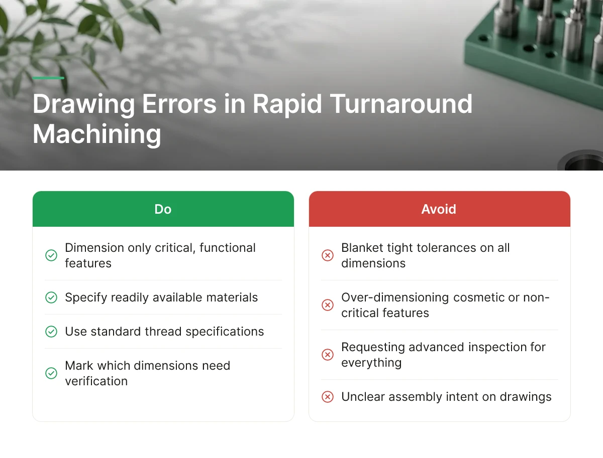
Five recurring drawing errors cause most of the delays and re-quotes we see in rapid turnaround machining services, and all five are avoidable with a five-minute review before submission.
Run your drawing package against this checklist before you send it out:
- Blanket tolerance blocks applied without regard to function. Setting every dimension to ±0.001 in. because that’s the title block default forces a shop to machine and inspect the entire part to the tightest spec, not just the features that need it. This is the single biggest driver of inflated quotes and slower cycle times, since tight tolerances demand slower feeds, more tool changes, and more inspection time. Tolerance only what actually affects fit, function, or assembly.
- Missing or ambiguous material and finish specifications. A callout like “aluminum” or “black finish” without an alloy grade, temper, or finish standard forces the shop to stop and request clarification before quoting can even start. Name the exact spec, 6061-T6, Ra 32 µin, black anodize per MIL-A-8625 Type II, so the request for quote moves straight to review.
- Requirements buried in secondary documents or verbal instructions. Emails, spec sheets, and phone calls get lost or misread once a job moves to the shop floor. Put every requirement, material, finish, critical dimensions, inspection method, directly on the drawing itself, since that is the one document that travels with the part through every stage of production.
- Inconsistent or duplicated call-outs across views. When the same feature is dimensioned differently in the front view and the section view, the machinist has to guess which one governs, or stop and ask. Consolidate call-outs so each feature is specified once, in the clearest view, with no conflicting duplicates.
- Failing to flag which dimensions are actually critical. If every dimension looks equally important, a quality team has no way to prioritize inspection and ends up measuring everything at the tightest assumed tolerance. Mark critical-to-function dimensions clearly, with GD&T or a simple critical-dimension callout, so inspection time goes where it matters.
None of these fixes require new software or a redesign. They require a second pass over the drawing before it leaves your desk. At MFG SOLUTION, drawings that clear this checklist move through our 8-hour quoting process without a clarification round-trip, which is often the difference between a 3-day ship window and a delay measured in weeks.
Frequently Asked Questions
What are the most common drawing annotation mistakes that delay CNC jobs?
Missing thread callouts, unclear datum references, and over-toleranced non-critical features cause the most quoting delays and machining stoppages. Programmers stop to request clarification when a hole lacks tap size and depth, or when GD&T conflicts with a plain dimension. Consolidating repeated callouts into a single note, as recommended for multiples of the same feature, also prevents misreads that trigger scrap or rework.
Why should I limit references to secondary documents in my technical drawings?
Every external document a machinist must open adds lookup time and a chance for version mismatches between the drawing and the referenced spec. Keeping critical specs directly on the drawing reduces interpretation errors and speeds up quoting, since reviewers work from one self-contained document instead of chasing linked files.
How do I dimension only the critical and measurable features that matter for assembly?
Dimension the features that control fit, function, or assembly interfaces, and leave general geometry to standard tolerance notes. Flag mating surfaces, hole locations tied to other parts, and sealing diameters explicitly. Everything else can carry a block tolerance, which cuts inspection time without risking assembly failures downstream.
How do I annotate drawings to ensure quality control processes don’t create bottlenecks?
Mark only the dimensions that require inspection, and specify the measurement method when it’s not obvious from the drawing alone. Over-tolerancing forces inspectors to check features that don’t affect function, slowing first-article approval. Clear, minimal annotation lets a shop working to ISO 9001:2015 or IATF 16949 process controls move straight from print review to production.
Conclusion
Fast quoting and short lead times depend on what’s on your drawing before it ever reaches a shop floor. Dimension only what controls fit and function, keep thread and tolerance callouts on the print instead of buried in secondary documents, and consolidate repeated notes so reviewers read the part once, correctly. A drawing built this way is what lets a provider like MFG SOLUTION return a quote within 8 hours and ship within 3 days. Pull your last rejected or delayed print and check it against these four habits before you submit your next RFQ.
Recommended Articles
Explore more from our content library: