
2026-10-21
How to Prevent Warping in Aluminum Parts Manufacturing

Warping in aluminum parts manufacturing is prevented by matching the right alloy to the part’s geometry, controlling heat during machining, and relieving internal stress before final cuts. Thin-walled or asymmetric parts under 38mm are most at risk because uneven material removal releases stresses unevenly, pulling the part out of tolerance. The fix combines alloy choice (6061 resists distortion better than 7075 in most thin sections), balanced roughing/finishing passes, proper fixturing that doesn’t clamp-stress the part, and verified quality checks before shipping.
Select the Right Aluminum Alloy for Your Precision Part
The alloy you specify determines how a part cuts, how it holds tolerance, and how likely it is to warp during or after machining. Getting this choice right at the design stage prevents most of the defects that show up later in aluminum parts manufacturing. For a deeper breakdown of alloy grades and their properties, this aluminum machining grades and properties guide is a useful reference point before finalizing a spec.
6061 vs 7075 vs 5083: Key Differences for Small Precision Parts
6061, 7075, and 5083 cover most precision machining jobs, but they behave very differently under a cutting tool. 6061 is a heat-treatable, medium-strength alloy with good corrosion resistance and the most predictable response to machining stress, which is why it shows up constantly in connectors, housings, and fittings under 38mm. 7075 is heat-treatable and far stronger, some tempers approach the tensile strength of mild steel at a fraction of the weight, but that strength comes from an internal stress state that releases unevenly once material is cut away, raising distortion risk in thin sections. 5083 is a non-heat-treatable, magnesium-based alloy prized for corrosion resistance in marine and structural use, but it work-hardens during cutting and tends to produce rougher finishes than 6061 or 7075 at comparable speeds.
For parts with thin walls or tight tolerances, the deciding factor isn’t peak strength, it’s how calmly the material releases internal stress as you remove stock. 6061 is generally favored for these geometries because its stress relief is more uniform, leaving fewer surprises after roughing passes. Choosing the right alloy at this stage is one of the most reliable ways to keep aluminum parts manufacturing on schedule, since reworking a batch after warping shows up costs far more time than selecting carefully upfront. Resources like this precision aluminum alloy machining overview walk through how alloy composition affects dimensional stability in more detail.
How Alloy and Machinability Affect Cost and Timeline
Hardness and thermal conductivity drive tool wear, achievable cutting speed, and heat buildup at the cutting edge. Aluminum alloys machine fast compared to steel or stainless because of high cutting speeds, low tool wear, and clean chip formation, but that advantage narrows as alloy hardness rises. Harder, higher-strength grades like 7075 generate more cutting heat and localized stress, which raises warping risk on small, thin features if speeds and feeds aren’t adjusted. Softer, highly machinable grades like 2011 run at the highest speeds on screw machines and Swiss lathes but trade away the strength needed for structural applications. This guide to machining aluminum processes, challenges, and applications breaks down how these tradeoffs play out across different part types.
This directly affects project timelines. A harder alloy that needs slower cutting speeds, more conservative depth of cut, and extra finishing passes adds cycle time per part, and that adds up fast across a production batch. Choosing an alloy matched to the part’s actual strength requirement, rather than defaulting to the strongest option, is often the simplest way to protect both tolerance and delivery schedule in aluminum parts manufacturing.
Choose a Machining Process That Fits Your Part Geometry
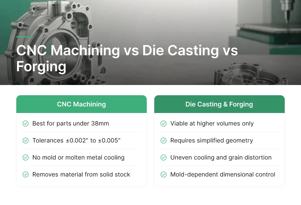
For parts under 38mm, CNC machining delivers the tightest dimensional control, while die casting and forging only make sense once volume climbs and geometry simplifies. Picking wrong on this decision is the single biggest cause of warping complaints and scrapped batches in aluminum parts manufacturing.
CNC Machining vs Die Casting vs Forging for Parts Under 38mm
CNC machining removes material from solid stock in controlled passes, which is why it holds tolerances as tight as ±0.002″ to ±0.005″ on small aluminum parts. There’s no mold, no molten metal cooling unevenly, and no grain flow distortion to manage, the part stays dimensionally stable because you’re cutting, not casting or pressing. That makes CNC turning, Swiss lathe, and CNC mill-turn operations the default choice for small, geometrically complex parts, especially in low-to-mid volume runs where tooling a die or forging stamp wouldn’t pay for itself. For a closer look at alloy selection for CNC work specifically, this guide on choosing the right alloy for CNC parts covers how to match grade to application.
Die casting and forging fit a different job entirely. Die casting excels at high-volume production of simpler geometries, think housings or brackets without tight internal features, but the cooling cycle inside the mold introduces shrinkage and uneven cooling rates that push tolerances wider and raise warping risk on thin-walled sections. Cold forging, by contrast, compresses aluminum into a die under pressure, which strengthens the grain structure and suits parts needing higher mechanical strength without heavy machining. Both processes trade some dimensional precision for throughput, which is fine for simple shapes at volume but risky for anything with tight-tolerance features under 38mm.
Cost and Timeline Tradeoffs Between Methods
CNC machining tends to run in the premium tier on a per-part basis at low volumes because every part is individually cut, but it carries no tooling investment, so lead times stay short and setup is fast. Die casting and forging require upfront die or mold costs that only pay off at volume, budget-friendly per part once you’re running thousands of units, but a slow, expensive start if your production run doesn’t justify the tooling.
This is why MFG SOLUTION runs CNC turning, Swiss lathe, cold forging, automatic lathe, and CNC mill-turn side by side: matching the process to the part, rather than forcing every job through one method, is what keeps cost and precision balanced for parts up to 38mm in aluminum parts manufacturing.
The decision framework comes down to three variables: part complexity, tolerance requirements, and production volume. Complex geometry with tight tolerances points to CNC machining regardless of volume. Simple geometry at high volume opens the door to die casting or forging. Anything in between needs a direct comparison of your drawing against both options before committing tooling budget.
Control Heat and Stress During Aluminum Parts Manufacturing to Prevent Warping
Warping in aluminum parts manufacturing almost always traces back to two causes: uneven stress release during cutting and excess heat buildup in thin sections. Controlling both requires deliberate sequencing, not just a sharp tool and a fast spindle.
What Causes Warping and Other Defects in Precision Aluminum Parts
Aluminum bar and plate stock carries locked-in internal stress from the rolling or extrusion process that made it. When a cutting tool removes material unevenly, more from one face than the other, or more from one side of a thin wall than the opposite side, that stress releases asymmetrically, and the part bends or bows to find a new equilibrium. This shows up most in thin-walled housings, long slender shafts under 5mm, and parts with asymmetric pocket geometry, where one side has far less material left to resist the stress shift than the other.
Heat compounds the problem. Aluminum’s thermal expansion rate is roughly double that of steel, so localized heat from aggressive cuts expands a thin wall during machining; when it cools, it contracts unevenly and locks in a dimensional error that inspection catches only after the part is off the machine. Clamping adds a third failure mode: a fixture that over-constrains a thin or flexible part holds it in a stressed, slightly deformed shape during cutting, and the part springs back out of tolerance the moment it’s released. Thermal distortion isn’t unique to machining, either; this resource on aluminum welding best practices for avoiding warping and cracking covers similar heat-management principles for joining operations.
How Process Control and Material Handling Prevent Defects
Preventing these defects starts with sequencing, not heroics. A rough-then-finish workflow, removing the bulk of the material first, pausing to let the part stabilize at room temperature, then taking light finishing cuts, gives residual stress a chance to release before the final dimensions are cut, rather than after.
- Rough first, stabilize, then finish. Separate roughing and finishing operations with a cooldown period so stress relief happens before final tolerances are machined, not during.
- Design fixtures that locate, not squeeze. Use light, distributed clamping forces and support points matched to the part’s geometry so the fixture doesn’t bend the part into a false shape that springs back after release.
- Control coolant flow and cutting speed. Flood coolant on thin walls and dial back feed rates in high-heat zones to limit localized thermal expansion that distorts the section once it cools.
- Balance the toolpath. Alternate cuts symmetrically across a part rather than roughing one side completely before moving to the other, so stress releases evenly instead of pulling the part in one direction.
These practices only work when they’re built into the process plan before the first chip comes off, which is why process documentation matters as much as the cut itself. MFG SOLUTION builds rough-finish sequencing, fixture design, and toolpath balancing into its process control plans under ISO 9001:2015 and IATF 16949, so warping risk is addressed during planning for parts up to 38mm in diameter, not caught at final inspection. For aluminum specifically, tolerances in the ±0.002 to ±0.005 inch range are achievable when this sequencing is followed, but skipping the stabilization pause is one of the most common ways that target gets missed in aluminum parts manufacturing.
Verify Quality Through Certification and Inspection
Certifications tell you how a supplier controls its process; inspection data tells you whether that control actually caught the defect in your specific batch. Both matter, and conflating them is a common mistake in aluminum parts manufacturing.
What ISO, AS9100, and ITAR Certifications Mean for Your Part
ISO 9001:2015 requires a documented quality management system, written procedures, recorded inspections, and traceable corrective actions when something goes wrong. It doesn’t guarantee a defect-free part, but it forces a manufacturer to prove, on paper, that every process step from material receipt to final inspection is controlled and repeatable. AS9100 builds on that foundation with aerospace-specific requirements around configuration management and risk assessment, which matters if your aluminum components feed into flight-critical assemblies.
ITAR compliance is often misunderstood as a quality marker. It isn’t. ITAR governs how a manufacturer handles, stores, and transmits information about defense-related parts, who can access drawings, where data can be sent, which personnel can touch the job. A supplier can be ITAR-registered and still have mediocre dimensional control, or ISO-certified with no ITAR registration at all. Ask about both separately, because a sales rep who blends the two into one pitch is giving you a shortcut, not an answer.
For medical device programs, ISO 13485:2016 adds requirements for risk management and device-specific traceability, and for automotive suppliers, IATF 16949 layers in defect-prevention metrics and continuous-improvement reviews on top of the ISO 9001 base.
How Quality Assurance Prevents Defects and Ensures Spec Compliance
Warping and dimensional drift typically show up during machining, not after, which is why in-process inspection matters more than a single final check. A coordinate measuring machine (CMM) checks critical dimensions mid-run, catching thermal distortion or fixture shift before a full batch is cut. First-article inspection verifies the very first finished part against the drawing in full detail before volume production starts, so an error gets caught on part one, not part 500.
Surface finish and tolerance verification round out the process: precision shops typically hold tolerances in the thousandths of an inch range for small aluminum components, and inspection reports should document actual measured values against the specified range, not just a pass/fail stamp.
More rigorous inspection and broader certification coverage add cost and, in some cases, a few days of lead time, since first-article documentation and CMM cycles take real machine and labor hours. MFG SOLUTION builds this into its process by manufacturing to ISO 9001:2015, ISO 13485:2016, and IATF 16949 standards with full process control, every step tracked and documented, while still quoting within 8 hours and shipping within 3 days.
Common Mistakes to Avoid When Manufacturing Small Aluminum Parts
Most defects in aluminum parts manufacturing trace back to five decisions made before the first chip is cut: alloy choice, process sequencing, fixturing, inspection timing, and process-volume fit.
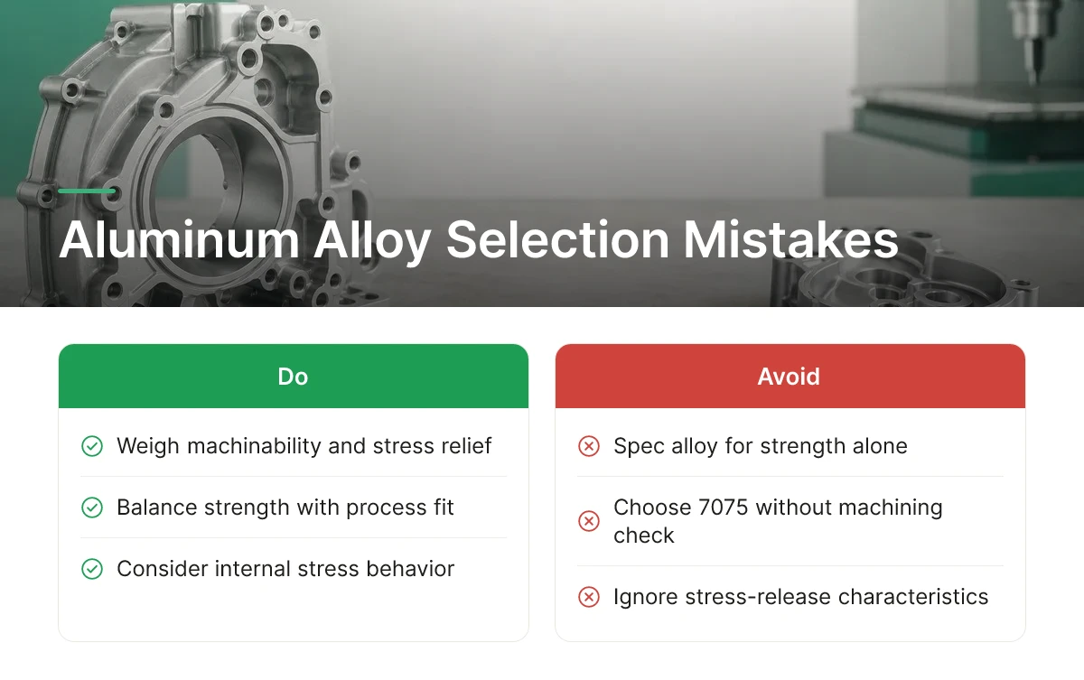
- Picking alloy for strength alone. Engineers often spec 7075 because it approaches the tensile strength of mild steel at one-third the weight, then discover it machines less predictably and releases more internal stress than 6061 or the non-heat-treatable 2011 grade optimized for high-speed screw machine work. Alloy selection has to weigh machinability and stress-relief behavior alongside strength, not instead of it, the wrong grade for your geometry turns an easy job into a warping problem.
- Skipping stabilization between roughing and finishing. Roughing removes material unevenly and releases locked-in stress from the mill or extrusion process. On thin walls or asymmetric shapes, machining straight from roughing to finishing without a stress-relief or stabilization pass lets that residual stress relax mid-process, distorting the part after it already passed inspection.
- Over-clamping thin sections. Fixtures that over-tighten or clamp unsupported thin walls hold the part in a stressed position during cutting. Once released, the material springs back, a common, avoidable cause of out-of-tolerance parts that looked fine on the machine and failed on the inspection table.
- Not asking about in-process checkpoints. If your supplier only measures at final inspection, warping or drift can go undetected through several operations before anyone catches it. Ask what gets checked between roughing, stress relief, and finishing, not just at the end. Full process control, with every step tracked and documented, is what catches a bad part on station three instead of after it ships.
- Mismatching MOQ and lead time against process. Expecting die-cast-style volumes and unit costs from a CNC turning or Swiss lathe run sets up disappointment on both sides. CNC and Swiss processes suit small-to-mid batches with fast turnaround; die casting suits high volume with longer tooling lead times. Confirm which process your quote assumes before committing to a delivery date.
MFG SOLUTION addresses these failure points directly: quotes list the recommended process among CNC turning, Swiss lathe, cold forging, automatic lathe, or CNC mill & turn based on your part’s geometry and volume, and production runs under ISO 9001:2015, ISO 13485:2016, and IATF 16949 process control catch dimensional drift before final shipment rather than after, a discipline that separates reliable aluminum parts manufacturing from shops that only inspect at the end.
Frequently Asked Questions
What are the key differences between 6061, 7075, and 5083 aluminum for small precision parts?
6061 balances machinability, strength, and corrosion resistance for general precision parts; 7075 offers much higher strength, approaching some mild steels at a third the weight, but costs more and machines less forgivingly. 5083 is a non-heat-treatable, marine-grade alloy favored for corrosion resistance over raw strength. Choosing among them depends on load requirements, environment, and whether post-machining heat treatment is practical for your geometry.
How do minimum order quantities and lead times vary across different manufacturing processes?
Swiss lathe and automatic lathe runs favor higher-volume batches, while CNC turning and mill-turn handle smaller runs or prototypes more economically. Cold forging typically needs higher minimums to justify tooling. MFG SOLUTION issues quotes within 8 hours and ships within 3 days regardless of process, which shortens the sourcing cycle significantly compared to traditional multi-week vendor quoting.
What pricing models should I expect, and how do volume and complexity affect total cost?
Expect project-based, job-shop pricing rather than fixed catalog rates, since cost depends on alloy, tolerance, and batch size. Higher volumes lower per-part cost by spreading setup and tooling expense, while tight tolerances or complex geometries push cost up regardless of volume. Choosing the right process among CNC turning, Swiss lathe, cold forging, automatic lathe, or mill-turn is often the biggest lever for controlling total cost on parts under 38mm.
Can warped aluminum parts be corrected after machining, or must they be scrapped?
Minor warping can sometimes be corrected with stress-relief heat treatment or re-machining, but severe distortion usually means scrapping the part. Prevention beats correction: proper fixturing, balanced cutting passes, and stress-relieving before final machining avoid most warping issues addressed in welding and machining guidance.
How does part geometry influence the choice of alloy and process in aluminum parts manufacturing?
Thin walls, deep pockets, and asymmetric features are more prone to stress-related distortion, so geometry often narrows the alloy and process choice before cost or volume even enter the conversation. Simple, symmetric shapes tolerate a wider range of alloys and methods, while complex or thin-walled designs usually push toward 6061 and CNC machining specifically because both offer more predictable, controllable outcomes in aluminum parts manufacturing.
Conclusion
Getting aluminum parts right comes down to three decisions made before a single chip is cut: match the alloy to the load and environment, choose the machining process that fits your tolerance and volume, and build in stress-relief steps that prevent warping rather than fixing it after the fact. Skipping any one of these invites rework, scrap, or missed deadlines in aluminum parts manufacturing.
Start your next run by sending a drawing with alloy, tolerance, and quantity specified to a certified machining partner, MFG SOLUTION returns quotes within 8 hours, so you can compare process options before committing production time.
Recommended Articles
Explore more from our content library: