
2026-10-18
A Practical Guide on How to Design for Manufacturing

Understanding how to design for manufacturing is essential. Design for manufacturing (DFM) means designing precision machined parts so they can be produced reliably within your CNC equipment’s capabilities, tolerances, and cost targets, before the design ever reaches the shop floor. It matters because features that look fine on screen (deep thin-walled pockets, tight tolerances on non-critical surfaces, hard-to-reach internal geometry) often require extra setups, slower feeds, or special tooling that drive up cost and lead time. Applying DFM early lets engineers catch these issues during design review, not during a quoting delay or a failed first article.

What Is Design for Manufacturing and Why Does It Matter for Precision Machining?
DFM, also called design for manufacturability, means matching a part’s geometry, tolerances, and material choices to what a CNC turning or milling process can actually hold, not just what a CAD model allows. A screen doesn’t care if a tool can reach a pocket, hold a wall thickness, or cut a thread at 2mm diameter. A Swiss lathe or 5-axis mill does. This is particularly relevant for how to design for manufacturing.
Learning how to design for manufacturing starts with understanding why a change is cheap on screen and expensive on the shop floor. Moving a dimension line or loosening a tolerance in CAD takes seconds. The same change discovered after tooling is cut, fixtures are built, or a first article fails inspection means scrapped setup time, a new round of programming, and a delayed ship date. The cost of a design decision doesn’t stay flat as it moves downstream, it compounds at every stage the error survives undetected.
How Does Design for Manufacturing Differ from Design for Assembly or Design for Cost?
DFM governs how a single part gets made; design for assembly and design for cost govern what happens after that part leaves the machine. Design for assembly focuses on how multiple components fit and join, snap features, fastener access, stack-up tolerances across an assembly. Design for cost looks at the broader bill of materials: sourcing decisions, make-versus-buy calls, material substitutions across an entire product line. For a broader overview of these distinctions, this guide to optimizing product development through DFM breaks down how each discipline fits into the larger process.
DFM sits upstream of both. It answers one question: can this specific geometry, at this tolerance, in this material, be cut reliably on the equipment available? Get that wrong and assembly fit and total program cost become moot, the part never clears first article inspection.
What Cost and Timeline Benefits Can You Expect from Applying DFM Principles?
Parts designed with manufacturability in mind generate fewer quote revisions, fewer engineering change orders, and reach first article faster than parts that require back-and-forth clarification after submission. Each round of “can you confirm this tolerance” or “this wall thickness isn’t holding” adds days to a program before a single chip gets cut. A design that already reflects achievable tolerances and tooling access skips that cycle entirely.
At MFG SOLUTION, quotes return within 8 hours and approved orders ship within 3 days, timelines that depend on designs arriving largely manufacturable from the start, since any back-and-forth over tolerances or fixturing eats directly into that window.
Why Tight-Tolerance Small Parts Need DFM More Than Large or Simple Ones
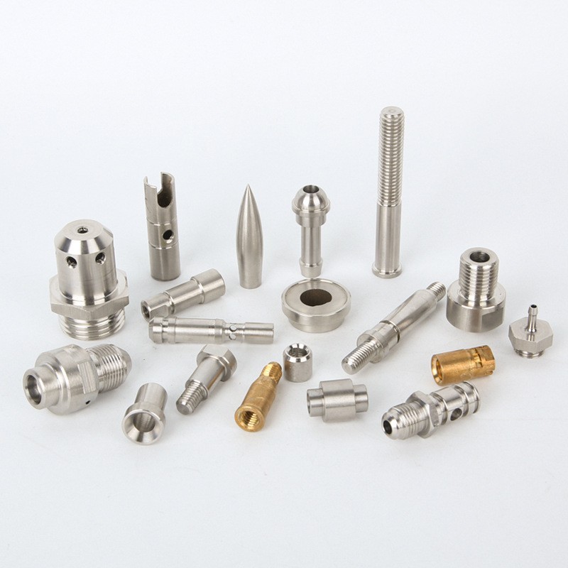
A 200mm bracket with ±0.5mm tolerances has room for error that a 15mm shaft with ±0.01mm tolerances does not. Small precision components, the kind machined on Swiss lathes and automatic lathes for electronics, medical, and automotive applications, leave almost no margin for a design choice that ignores tool deflection, material springback, or minimum wall thickness. The smaller the part and tighter the tolerance band, the more a five-minute design review upfront saves against a failed batch downstream.
What Are the Core Principles of Designing Parts for CNC Manufacturability?
Machinable parts balance four variables, tolerance, wall thickness, feature complexity, and material, so the cutting tool can remove stock at a steady rate without deflecting, chattering, or burning out. Get the balance wrong on any one of these and cycle time, scrap rate, or cost climbs fast. Learning how to design for manufacturing starts with understanding why these four variables interact instead of treating each as a separate checklist item.
How Do Tolerances, Wall Thickness, and Feature Complexity Affect Machinability on Small Precision Parts?
Tolerances tighter than the part actually needs are the most common and most expensive design mistake we see. A tolerance of ±0.01mm on a surface with no mating function forces slower spindle speeds, more frequent tool changes, and added inspection steps, sometimes a secondary grinding or lapping operation that a looser spec would have avoided entirely. Reserve tight tolerances for the features that control fit, seal, or function; let everything else run at standard commercial tolerances.
Wall thickness is the second lever. Thin walls on small parts, anything under roughly 0.5mm relative to the part’s overall diameter, flex under cutting force, producing chatter marks, dimensional drift, and warping once the part is unclamped and residual stress releases. Swiss lathe and CNC turning processes can hold thin sections better than standard three-axis milling because the material stays supported closer to the cut, but thin walls still raise scrap risk regardless of method.
Feature complexity compounds both problems. Deep pockets, sharp internal corners, and small-diameter holes that exceed typical length-to-diameter tool ratios all force slower feeds, smaller stepovers, and sometimes custom tooling. This overview of design for manufacturing fundamentals covers similar geometry constraints in more depth for engineers new to DFM. When considering how to design for manufacturing, this point stands out.
What Design Features Should You Avoid or Modify to Stay Within Typical CNC Capabilities?
- Sharp internal corners, add a radius matching available end mill or insert geometry; a true 90-degree internal corner is not achievable with round cutting tools.
- Undercuts, require specialized tooling or multi-axis setups; redesign as through-features where function allows.
- Inconsistent wall sections, abrupt thickness changes create uneven cooling and warping during machining.
- Threads placed too close to edges, risk chipping and reduce thread strength; leave adequate runout space.
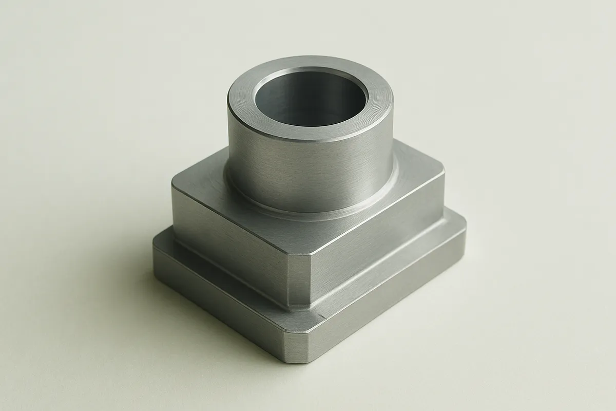
Material choice amplifies all of these rules. A hardened stainless or titanium alloy turns a tight tolerance or thin wall from a minor cost adder into a major one, since harder materials demand slower cuts and more tool wear to hold the same spec. We run five processes, CNC turning, Swiss lathe, cold forging, automatic lathe, and CNC mill & turn, on parts up to 38mm, which lets us match the process to the material and geometry instead of forcing one method to do everything.
How Do You Implement Design for Manufacturing in Your Product Development Workflow?
Implementing DFM means building checkpoints into each development stage, concept, prototype, design freeze, first article, where manufacturing input shapes the design before it hardens into a drawing. This overview of collaboration starting from the upstream describes a similar staged approach to bringing manufacturing knowledge into early design decisions.
Most teams that struggle with how to design for manufacturing treat it as a final review step rather than a workflow. By the time a drawing reaches that review, geometry, tolerances, and material choices are already locked in people’s heads, even if nothing is officially frozen. Reworking a design at that point costs more in time and credibility than most engineers want to admit.
At What Stage of Product Design Should You Involve Manufacturing Input, and How?
Bring manufacturing input in at the concept sketch or early CAD stage, not after drawings are finalized, because early feedback changes geometry decisions cheaply while late feedback forces redesigns.
A practical staged workflow looks like this:
- Concept sketch: Rough geometry and function are defined. A quick conversation with a machinist flags obvious problems, wall thicknesses too thin for turning, features that need a fourth axis, bosses that will trap coolant.
- DFM review: Before tolerances are finalized, the design engineer shares CAD files with a machining partner for a manufacturability pass. This is where features get simplified, tolerances get tightened only where functionally necessary, and the team agrees on which process, CNC turning, Swiss lathe, cold forging, fits the part.
- Prototype: A small batch validates fit, function, and the assumptions made during the DFM review. Iterative prototyping matters here because some manufacturability issues, chatter on a thin-walled feature, a tolerance stack-up that only shows up under load, don’t surface until a physical part exists.
- Design freeze: Geometry and tolerances are locked. Any change after this point goes through a formal revision, not an email thread.
- First article inspection: The first production-representative part is measured against the drawing, confirming the process can hold the specified tolerances repeatably before the full batch runs.
Cross-functional review is what makes each checkpoint work. A design engineer focused on fit and function may miss that a specified tolerance requires a secondary grinding operation; a machinist unfamiliar with the assembly’s functional requirements may suggest a simplification that breaks a mating part. Reviewing together catches what neither catches alone.
At MFG SOLUTION, this early-input approach is built into the quoting process, CAD files submitted for a quote get evaluated by engineers across turning, milling, and forging methods within 8 hours, so manufacturability feedback arrives before tolerances are locked, not after a batch fails first article inspection.
What Are the Common DFM Mistakes That Increase Costs and Delay Delivery?
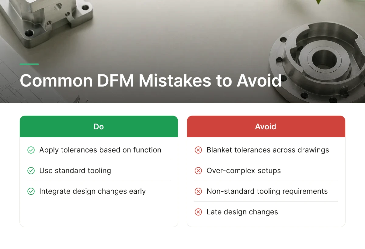
Four mistakes drive most of the avoidable cost in precision machining: blanket tolerances, over-complex setups, non-standard tooling requirements, and late design changes. Each one adds machine time, scrap risk, or rework, and each is preventable once you know what to look for when you learn how to design for manufacturing.
Blanket Tolerances Instead of Functional Tolerancing
Copying a tight tolerance block across an entire drawing, say, ±0.01mm on every dimension because that’s the company template, forces secondary operations like grinding or honing on features that never needed them. A bore that locates a bearing might genuinely need tight control; a chamfer or a non-mating edge does not. Every unnecessary tight tolerance adds inspection time, slows cycle time, and raises scrap rates, because tighter tolerances mean tighter process windows and more rejected parts. The fix is tolerancing only the features that affect fit, function, or assembly, and leaving the rest at standard shop tolerance.
Geometry That Demands Excessive Fixturing or Multiple Setups
Features located on opposing faces, odd clamping surfaces, or asymmetric datums often force a part through three or four separate setups instead of one. Each additional setup adds machine time and, more importantly, introduces a new opportunity for misalignment between features machined in different operations. A part that could be held and finished in a single Swiss lathe operation, but is instead designed with features scattered across multiple faces, will cost more and carry tighter risk of out-of-spec stack-up. For those exploring how to design for manufacturing, this matters.
Ignoring Standard Tool Sizes
Specifying a hole diameter or thread pitch that falls outside standard drill, tap, or reamer sizes forces the shop to source or grind custom tooling. That single decision can add lead time and tooling cost to an otherwise routine part. Designing to standard tool libraries, or asking a supplier which sizes they stock, avoids this entirely.
Late Design Changes After Tooling or Programming Has Started
Once CNC programs are written and tooling is set up, a geometry change means reprogramming, new fixtures, and often new cutting tools, all billed as rework rather than normal production cost. Locking design intent before programming begins is one of the simplest ways to protect both budget and delivery date. This comprehensive overview of design for manufacturing walks through similar cost drivers in greater detail.
How Can You Troubleshoot When Your Design Team and Manufacturing Team Disagree on Manufacturability?
Trace the disagreement to one specific feature, quantify the exact manufacturing constraint behind it, then propose alternative geometry that preserves the original function. If a designer wants a deep, narrow slot and the machinist objects, the real issue is usually tool reach or deflection at that length-to-diameter ratio, not a vague “it’s hard to make.” Once you quantify the constraint, the fix is usually an alternate radius, a split feature, or a relieved pocket that performs the same job. MFG SOLUTION’s engineering team reviews submitted specifications against its CNC turning, Swiss lathe, and mill-turn capabilities before quoting, so disagreements get resolved before tooling starts, not after.
What Tools and Software Help You Validate Designs for Manufacturing Before Production?
CAD-integrated checkers, machining simulators, and automated quoting engines catch manufacturability problems on screen, before a single part gets cut on a machine.
These three categories cover most of what engineers need when learning how to design for manufacturing without relying on trial and error at the machine. Each works at a different stage of the design, and the strongest workflows use all three in sequence.
CAD-Integrated DFM Analysis
Plug-ins built into CAD environments flag thin walls, tight tolerances, and inaccessible features while the designer is still modeling the part, not after it’s released to a shop. Instead of exporting a drawing and waiting for feedback, the engineer sees a warning the moment a wall drops below a safe thickness or a hole depth exceeds a reasonable ratio to its diameter. This is the layer most design for manufacturability guidance points to first, because the earlier a flaw surfaces, the cheaper it is to fix. Some tools check geometry against generic rules; others let a shop load its own machine limits so the checks reflect actual tooling and tolerance capability rather than textbook defaults.
Machining Simulation Software
Simulation software models the toolpath itself, predicting collisions, tool deflection, and excessive cycle time before a program ever touches raw stock. A simulated run shows where a long, thin tool might chatter against a deep pocket, or where a fixture clamp would collide with the spindle mid-cycle. For parts machined on multi-axis equipment, this step matters more, since a collision on a 5-axis CNC machine can damage tooling and the part in the same pass.
Automated Quoting as a Manufacturability Check
Automated quoting tools that read CAD files directly can surface manufacturability flags as a byproduct of pricing the job, giving engineers feedback before they commit to a design. If a feature would require a slower process or a secondary operation, the quote reflects that cost difference, which tells the designer something a drawing review alone would not. MFG SOLUTION applies this principle in its own workflow: uploaded specifications get a quote within 8 hours, and that turnaround depends on the same file analysis that would catch a tolerance or feature mismatch against its CNC turning, Swiss lathe, cold forging, automatic lathe, or mill-turn capabilities.
How Do CAD Integration and Simulation Platforms Reduce Design-to-Production Cycle Time?
Catching a problem in simulation costs a few minutes of review; catching the same problem on a physical first article costs a scrapped part, a delayed schedule, and a new design iteration. Simulation and CAD-integrated checks shorten the design-to-production cycle because they compress that feedback loop from days to minutes. Each round of physical trial and error, by contrast, typically adds a full production or shipping cycle before the engineer even sees the result.
Tool sophistication varies widely, from basic geometry-checking plug-ins bundled free with common CAD packages to premium simulation suites used for complex multi-axis programming. Neither tier replaces direct communication with the shop that will actually cut the part, but both reduce how many surprises show up after the order is placed. This directly impacts how to design for manufacturing outcomes.
Frequently Asked Questions
What is design for manufacturability in simple terms?
Design for manufacturability means shaping a part’s geometry, tolerances, and material choice so a shop can machine it efficiently without sacrificing function. Instead of designing a part in isolation and hoping it can be produced, you check each feature against real CNC, Swiss lathe, or cold forging constraints before the drawing goes final. The goal is fewer surprises in quoting, tooling, and inspection.
Does DFM apply differently to prototypes versus production runs?
Yes, prototypes tolerate looser DFM discipline than high-volume production, where small inefficiencies multiply across thousands of parts. A single prototype can justify extra setups or tighter tolerances since cost is absorbed once. At production volume, a feature that adds 30 seconds of cycle time or requires a secondary operation becomes a recurring cost on every unit, so DFM review gets stricter.
Who should own DFM review, design engineering or the machine shop?
DFM review works best as a shared responsibility between design engineering and the machine shop, not owned by either side alone. Designers understand functional requirements; machinists and process engineers understand what’s actually hard to hold, fixture, or finish. MFG SOLUTION’s quoting process routes specifications through engineering staff who flag manufacturability issues before a quote is returned within 8 hours, closing that loop early.
Can DFM principles change based on the material being machined?
Yes, material properties directly change which tolerances, wall thicknesses, and tool paths are realistic. Free-machining steels and brass behave differently under a Swiss lathe than stainless or titanium, which work-harden and demand different feeds, speeds, and tooling. A DFM review that ignores material behavior will underestimate cost or overestimate what’s achievable in one setup.
How early should DFM documentation be created in a new product program?
DFM documentation should start forming during the concept sketch phase, not after the first full drawing release. Capturing early decisions, why a tolerance was set, why a wall thickness was chosen, gives later reviewers context instead of forcing them to guess intent. Programs that document DFM reasoning early tend to resolve design disagreements faster during later review stages.
Conclusion
Designing for manufacturability comes down to three habits: specify tolerances only as tight as the part actually needs, pick geometry that matches a known process like CNC turning or cold forging, and get manufacturing input before the design is locked. Skipping that last step is what turns a routine order into a six-week back-and-forth over RFQs and redlines.
If you have a drawing ready, the fastest way to test it is to submit it for a real quote. MFG SOLUTION returns manufacturability feedback and pricing within 8 hours, so you find out what needs to change before it costs you a production run.
Recommended Articles
Explore more from our content library: