
2026-11-06
CNC Machining for Industrial Water Treatment Equipment: Pump Housings, Valve Bodies, Filter Components and Precision Fluid Interfaces
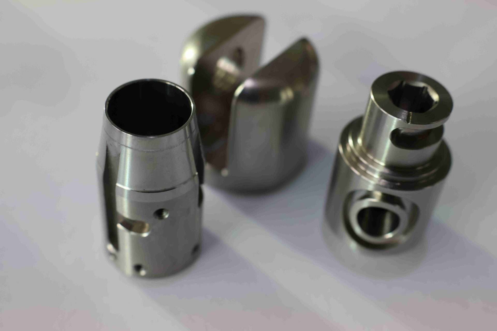
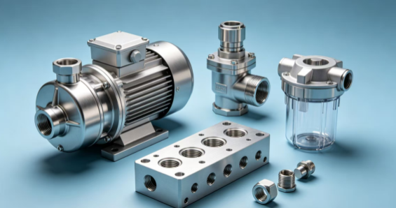
Industrial water treatment equipment operates under a wide range of conditions. Municipal water purification plants, industrial wastewater facilities, filtration systems, chemical dosing equipment and membrane treatment installations all depend on mechanical components that control fluid movement, maintain pressure and support reliable operation.
Behind these systems are numerous precision-manufactured parts. Pump housings guide fluid through internal passages. Valve bodies control flow and isolation. Filter housings provide structural support for filtration elements. Manifolds distribute liquids between different treatment stages. Connectors, adapters and sealing interfaces help prevent leakage between assembled components.
Although some of these parts appear relatively simple, their manufacturing requirements can be demanding. Internal passages must connect correctly, threaded ports must match the specified fittings, sealing surfaces must meet dimensional requirements, and materials must be compatible with the process fluid and operating environment.
CNC machining provides a flexible solution for manufacturing custom water treatment components. CNC milling, turning, drilling, boring and multi-axis machining can produce complex geometries, accurate interfaces and repeatable dimensions from metals and engineering plastics.
For equipment manufacturers and engineering teams, successful sourcing requires more than selecting a machining process. Material compatibility, pressure requirements, fluid-contact surfaces, dimensional tolerances, surface finishing and inspection must be considered together.
MFG SOLUTION supports custom precision manufacturing for industrial equipment applications. This guide explains the important manufacturing considerations for CNC-machined water treatment components, from design review and material selection to production planning, quality inspection and quotation.
1. Typical CNC-Machined Components in Water Treatment Equipment
Water treatment systems contain several connected stages, including pumping, filtration, chemical dosing, flow regulation and wastewater discharge. Each stage requires components with different mechanical and fluid-handling functions.
Pump housings and covers
Pump housings contain the internal geometry that guides liquid through a pumping assembly. Depending on the pump design, machined features may include inlet and outlet ports, mounting surfaces, bearing interfaces, shaft openings, cover connections and sealing grooves.
These features must be positioned according to the engineering drawing. The relationship between the shaft opening, bearing seat and pump housing geometry can influence assembly and operating performance.
CNC milling and boring are commonly considered for housings with complex pockets and precision bores. CNC turning may be used for cylindrical covers, sleeves and related rotational components.
The manufacturing strategy should account for material removal, wall thickness, workholding stability and the location of critical interfaces.
Valve bodies and flow-control components
Valve bodies regulate or isolate fluid movement. They may contain internal cavities, threaded ports, valve seats, mounting holes and connections for actuators or external fittings.
A valve body may require several machining operations to produce intersecting passages and accurately positioned openings. Burrs left inside accessible fluid passages can interfere with assembly or become a source of contamination.
The manufacturing drawing should clearly define port dimensions, thread specifications, sealing faces and relevant datum references.
Filter housings and filtration components
Filter equipment may use housings, end caps, support plates, retaining rings, adapters and cartridge connection components.
These parts can require accurate sealing grooves, threaded connections and locating surfaces. Depending on the filtration system, material selection may also need to consider cleaning chemicals, process temperature and the fluid contacting the component.
Membrane system connectors and manifolds
Membrane filtration equipment often contains multiple fluid connections and distribution interfaces. Manifolds and adapters may have several ports arranged across different faces.
The relationship between the ports is important. Incorrect positioning can complicate piping installation, create assembly conflicts or require additional adjustment.
For multi-face components, CNC milling and five-axis machining may help produce the required geometry while reducing unnecessary setup changes.
Chemical dosing and wastewater components
Chemical dosing systems use pumps, valves, fittings, seats, sleeves and other fluid-contact components. Wastewater equipment may also contain adapters, mounting blocks, covers and mechanical supports.
The selected material and surface condition should be evaluated against the actual chemical composition, concentration, temperature and pressure conditions. A material suitable for one treatment process should not automatically be assumed suitable for another.
2. Selecting Materials for Water Treatment Components
Material selection is one of the most important decisions in water treatment equipment manufacturing. Components may contact clean water, wastewater, cleaning agents, treatment chemicals or fluids containing suspended solids.
The material must satisfy the component’s mechanical requirements as well as its environmental and chemical compatibility requirements.
Stainless steel
Stainless steel is widely considered for industrial fluid-handling components because different grades offer useful combinations of strength, corrosion resistance and machinability.
Depending on the application, stainless steel may be used for valve bodies, pump interfaces, filter components, adapters, shafts and mounting parts.
However, stainless steel grades are not interchangeable. The selected grade should be reviewed against the process fluid, chloride exposure, cleaning chemicals, temperature and expected service conditions.
Machining characteristics also differ between grades. Cutting conditions, tooling, workholding and surface-finish requirements should be planned accordingly.
For further material information, see the MFG SOLUTION stainless steel block machining guide.
Aluminum alloys
Aluminum alloys can be suitable for selected equipment covers, brackets, mounting plates and non-critical fluid-handling structures where the operating environment permits their use.
Their relatively low density and good machinability can make them attractive for lightweight components. However, corrosion resistance and compatibility with the process fluid must be evaluated before selecting aluminum for direct fluid contact.
Thin-wall aluminum components may also be sensitive to clamping pressure and machining distortion.
Explore the aluminum machining resource for additional information.
Carbon and alloy steels
Carbon and alloy steels may be suitable for mechanical supports, shafts, mounting components and selected equipment structures.
Where the component is exposed to moisture or corrosive fluids, the material specification and protective treatment require careful review. A steel grade that performs well mechanically may still need additional corrosion protection in the intended environment.
The 1045 steel turned parts guide provides a reference for steel machining applications.
Engineering plastics
Engineering plastics can be useful for selected fluid-contact parts, valve seats, spacers, bushings, seals and insulating components.
Possible material choices include PTFE, PEEK, POM, nylon, PVC, PP and other grades, depending on the application.
The correct selection depends on chemical compatibility, temperature, pressure, mechanical loading, dimensional stability and wear conditions. Material names alone are not enough to establish suitability.
For example, a static sealing component may have different requirements from a moving valve guide or a pump bushing. The manufacturer should review the operating conditions and specified material grade before production.
MFG SOLUTION’s material selection resource can help engineering teams organize material requirements during design review.
3. CNC Milling for Valve Bodies, Manifolds and Filter Housings
CNC milling is suitable for components that contain flat surfaces, pockets, slots, mounting holes, cavities and complex external profiles.
Water treatment equipment frequently uses block-shaped components with several machined interfaces. A single valve body, for example, may contain multiple ports, threaded holes, mounting faces and internal flow passages.
Machining multiple faces
Some manifolds require connections on several sides. Their manufacturing sequence should consider tool accessibility, datum selection and the relationship between ports.
A suitable fixture can help locate the component consistently between operations. Where multiple faces must be machined, the number of setups should be evaluated against the accuracy and cost requirements.
Producing internal pockets and passages
Internal cavities and intersecting passages require attention to cutter access, drilling depth, tool length and chip removal.
The drawing should distinguish between critical flow passages and ordinary clearance features. Where passage intersections affect function, their position and geometry should be clearly specified.
Choosing conventional or five-axis machining
Three-axis milling can handle many conventional housing and manifold designs. Four-axis or five-axis machining may be appropriate when angled ports, complex faces or difficult tool access make conventional setups inefficient.
Five-axis machining is not automatically necessary for every manifold. The decision should reflect component geometry, production volume, tolerance relationships and total manufacturing cost.
Learn more about five-axis CNC machining and general CNC machining capabilities.
Controlling thin walls and clamping deformation
Some filter housings and covers have thin walls or uneven material distribution. Excessive clamping force can deform the workpiece, while aggressive material removal may create dimensional instability.
A stable workholding strategy, suitable machining sequence and appropriate finishing allowance help reduce these risks.
The CNC workholding fixtures guide explains common approaches to locating and supporting precision components.
4. CNC Turning for Shafts, Sleeves, Fittings and Adapters
CNC turning is suitable for cylindrical and rotational components used throughout water treatment systems.
Typical examples include pump shafts, sleeves, valve stems, threaded fittings, retaining collars, adapters and precision spacers.
Pump shafts and bearing interfaces
Pump shafts may contain several functional diameters, shoulders, grooves and threaded features. These dimensions can determine the position of bearings, seals and connected components.
The machining sequence should establish appropriate reference surfaces and maintain the relationship between critical diameters.
Where shaft concentricity or runout is important, the inspection plan should identify how these characteristics will be verified.
Valve stems and precision sleeves
Valve stems and sleeves may require accurate diameters, grooves and surface conditions to support movement and assembly.
The required fit depends on the design and the materials used in the mating components. Excessively tight or loose dimensions can affect operation, so the drawing should specify the functional requirements.
Threaded fittings and adapters
Fluid system fittings connect pipes, hoses, valves and equipment assemblies. Their threads and sealing features must match the specified connection standard.
The drawing should identify the thread type, pitch, diameter, engagement length and any sealing requirements.
A thread that appears dimensionally similar may not be compatible with another thread standard. This should be resolved during the RFQ review rather than after production.
See the precision thread tolerance guide for more information.
Swiss turning for small components
Small precision fittings, pins, sleeves and other rotational components may benefit from Swiss-type machining when their geometry and production quantities justify the process.
Review the Swiss turning guide for an overview of its applications.
5. Sealing Interfaces, O-Ring Grooves and Pressure-Related Features
Water treatment equipment often contains several connections where leakage prevention is important. These may include pump covers, valve connections, filter housings, manifold joints and threaded adapters.
Define sealing geometry clearly
Sealing performance depends on more than the nominal diameter of a component. The design may also involve groove width, groove depth, surface finish, flatness, mating dimensions and the selected sealing material.
The engineering drawing should provide the dimensions and tolerances required to manufacture and inspect these features.
Control sealing faces
A sealing face may require a specified surface finish and flatness. Scratches, burrs or local deformation can affect the mating interface.
However, not every external surface needs the same finish. The drawing should identify which surfaces perform a sealing function and which are non-critical.
Review pressure requirements
Components exposed to internal pressure require a design and verification approach appropriate to their intended service conditions.
Machining accuracy alone does not establish pressure integrity. The component design, base material, wall thickness, manufacturing route and any required pressure or leak testing should be defined by the responsible engineering specification.
Where pressure testing or other verification is required, include the acceptance criteria in the RFQ.
Avoid unnecessary tolerance stacking
A fluid assembly may contain several connected components. Dimensional variation can accumulate across interfaces, affecting installation and sealing.
Engineering teams should identify the critical dimensions that control the assembled condition. Tolerances should be assigned based on actual function rather than tightened uniformly across every feature.
For further information, read the machining tolerances guide and the guide to how CNC tolerance affects part pricing.
6. Hole Accuracy and Internal Fluid Passage Machining
Water treatment components frequently contain drilled ports, intersecting passages, mounting holes and precision bores.
The accuracy of these features can influence fluid routing, assembly and connection reliability.
Drilling and boring
Drilling is suitable for many standard holes. However, deeper or more demanding bores may require additional operations to achieve the specified diameter, alignment or surface condition.
Boring and reaming may be appropriate depending on the hole geometry and drawing requirements.
Cross-drilled passages
Manifolds and valve bodies may contain intersecting passages that connect different ports.
Their design should consider tool access, drilling depth, intersection position and the ability to remove machining chips. Where a passage intersection is difficult to inspect or clean, the design and manufacturing process should address that limitation.
Threaded ports and connection geometry
Ports may use different thread standards or connection arrangements. The drawing should identify the exact specification and any required sealing method.
Where ports are located on several faces, their position should be measured relative to the relevant datums.
See the CNC hole tolerance guide for more details about selecting hole-making operations.
7. Surface Finishing, Deburring and Fluid-Path Cleanliness
Surface treatment and post-machining operations can influence corrosion protection, sealing, appearance and component cleanliness.
Select surface treatment according to material
Different materials require different finishing approaches. Aluminum, stainless steel, carbon steel and engineering plastics cannot be treated as though they have identical surface requirements.
Depending on the component and application, possible treatments may include anodizing, passivation, plating, polishing or protective coating.
The selected treatment must be compatible with the base material and operating environment. It should also account for dimensional changes on precision interfaces.
Protect precision surfaces during finishing
Bearing bores, sealing faces, threaded ports and locating diameters may need masking or special handling during surface treatment.
If a coating changes the dimension of a critical interface, the manufacturing sequence must account for that effect.
Remove burrs from fluid passages
Burrs can remain around drilled holes, intersecting passages, milled edges and threaded ports.
For fluid-handling components, deburring should consider both accessible external edges and internal features. The required level of cleaning should be defined according to the equipment’s process and contamination-control requirements.
Specify surface roughness by function
A sealing surface may require a different finish from a general mounting face or non-functional exterior surface.
Avoid assigning an unnecessarily fine finish to every machined area. Functional requirements should guide the specification.
Read the CNC machining surface finish guide and surface finishing selection guide for further details.
8. Quality Inspection for Water Treatment Components
A reliable inspection plan should connect the engineering drawing with the component’s intended function.
For water treatment equipment, this may include dimensional inspection, material verification, thread checks, surface inspection and additional testing where specified.
Dimensional inspection
Depending on the component, inspection may cover:
- Pump housing bore diameters
- Shaft diameters and runout
- Valve seat dimensions
- Thread size and pitch
- Port position and spacing
- O-ring groove width and depth
- Mounting-face flatness
- Hole position and perpendicularity
- Overall component dimensions
- Specified surface roughness
The measurement method should be suitable for the tolerance and feature geometry. Calipers and micrometers may be adequate for ordinary dimensions, while bore gauges, thread gauges, height gauges and coordinate measuring machines may be needed for more demanding features.
Material documentation
Where required, material certificates and traceability records help verify that the supplied material matches the specified grade.
For fluid-contact applications, the buyer may also require documentation relating to the material specification or applicable compliance requirements. These should be agreed before production.
First-article inspection
First-article inspection is useful when a component is new, a drawing has changed or a production process needs validation.
It allows the manufacturer and customer to review important dimensions before repeat production begins.
Pressure and leak testing
Not every machined component requires pressure or leak testing. The need depends on its design, function and customer specification.
If testing is required, the RFQ should define the test method, pressure or operating conditions, duration where applicable and acceptance criteria. The inspection record should identify the tested component and relevant results.
For more information about manufacturing inspection, see the quality assurance standards guide and the ISO 9001 precision machining guide.
9. How to Control Manufacturing Cost and Improve Part Design
The cost of a CNC-machined water treatment component depends on material, geometry, machining time, setup requirements, finishing, inspection and order quantity.
Good design decisions can improve manufacturability without compromising essential performance.
Avoid unnecessary tight tolerances
Tighter tolerances can require additional finishing operations, specialized measurement equipment and more inspection time.
Identify the dimensions that directly influence sealing, alignment, connection fit and flow-system assembly. Apply the appropriate requirements to those features and avoid excessive restrictions on non-critical geometry.
Simplify internal passages where possible
Complex intersecting passages can increase machining difficulty and make deburring or inspection more challenging.
Where the equipment design permits, consider practical passage layouts that provide suitable tool access and reduce unnecessary machining operations.
Review wall thickness and stock allowance
Thin walls can create workholding and distortion challenges. Excessive material allowance can also increase machining time and waste.
The selected starting material should provide enough allowance for the required machining sequence while remaining economical.
Choose the right manufacturing process
Not every component needs five-axis machining or multiple specialized operations.
Simple turned parts may be produced efficiently through CNC turning. Block-shaped valve bodies may require milling and drilling. Complex multi-face components may justify five-axis machining.
The best process is the one that meets the functional requirements with an appropriate balance of quality, cost and production efficiency.
Consider quantity and repeat production
Prototype orders, small batches and repeat production programs may require different process planning.
Expected annual demand and batch size can influence workholding, tooling, setup planning and inspection strategy. Providing this information early can help the manufacturer prepare a more realistic quotation.
For additional cost-planning information, review the CNC machining cost analysis guide.
10. Preparing an RFQ for Custom Water Treatment Components
A complete RFQ helps the manufacturer understand the part’s geometry, operating environment and inspection requirements.
For a more accurate quotation, provide:
- Current 2D engineering drawings
- Matching 3D CAD models
- Material grade and condition
- Order quantity and expected repeat demand
- Critical dimensions and geometric tolerances
- Fluid-contact information
- Operating temperature and pressure requirements
- Chemical exposure or cleaning conditions
- Thread and connection specifications
- Sealing groove and mating-interface details
- Surface finish and treatment requirements
- Deburring and cleanliness requirements
- Inspection reports or certificates where required
- Packaging and delivery expectations
For fluid-contact parts, identify the process media as clearly as possible. A general description such as “industrial water” may not provide enough information if the component will contact cleaning chemicals, wastewater or a specific treatment solution.
If the component connects to an existing pump, valve, pipe or filtration assembly, include the mating drawing or relevant interface dimensions.
The drawing revision should also be clearly identified. If the 2D drawing and 3D model contain conflicting dimensions, resolve the discrepancy before production.
MFG SOLUTION provides custom precision manufacturing services for industrial components. Engineering and procurement teams can review the company’s manufacturing capabilities before submitting project requirements.
Use the MFG SOLUTION online quotation page to share drawings and request a manufacturing review.
Frequently Asked Questions
1. What water treatment equipment components can be CNC machined?
Common examples include pump housings, valve bodies, filter housing components, manifolds, adapters, fittings, shafts, sleeves, mounting plates and precision sealing interfaces. The suitable process depends on the component geometry, material and engineering requirements.
2. Which materials are suitable for water treatment equipment parts?
Stainless steel, aluminum alloys, carbon steel, alloy steel and engineering plastics may be suitable for different applications. The correct choice depends on the process fluid, chemical exposure, temperature, pressure, mechanical loading and required service life.
3. Is stainless steel always the best choice for water treatment components?
No. Different stainless steel grades have different corrosion resistance and machining characteristics. Material selection should consider the actual fluid chemistry and operating conditions. Other metals or engineering plastics may be more appropriate for certain components.
4. Why are sealing surfaces important in pump and valve components?
Sealing surfaces help maintain the intended connection between mating components. Their dimensions, flatness and surface condition can influence leakage performance. The drawing should define the required sealing geometry and inspection criteria.
5. Can CNC machining produce internal passages in valve bodies and manifolds?
Yes. CNC drilling, milling and related operations can produce specified passages and ports. The design should consider tool access, passage intersections, burr removal, chip evacuation and inspection accessibility.
6. Do water treatment components require pressure testing?
Not all components require pressure testing. The requirement depends on the component’s function and customer specification. If testing is necessary, the method and acceptance criteria should be agreed before production.
7. How can machining costs be reduced without affecting performance?
Useful approaches include applying tight tolerances only to functional features, simplifying passage geometry where possible, selecting suitable stock material, reducing unnecessary setups and defining practical finishing requirements.
8. What information should be included when requesting a quotation?
Provide current drawings, 3D models, material specifications, quantities, critical tolerances, fluid-contact conditions, surface requirements and inspection expectations. Mating-part information is also useful for components with sealing or connection interfaces.
Conclusion: Precision Manufacturing for Reliable Water Treatment Equipment
Water treatment equipment depends on components that must work together across pumps, valves, filtration units, chemical dosing systems and fluid distribution assemblies.
Pump housings, valve bodies, filter interfaces, manifolds and precision fittings each have different manufacturing requirements. Material compatibility, dimensional accuracy, sealing geometry, surface condition and inspection must be considered as part of one coordinated process.
The most effective manufacturing approach starts with a clear understanding of the component’s function and operating environment. Accurate drawings, suitable material selection, practical tolerances and an appropriate machining sequence can help reduce production risk and improve assembly consistency.
For engineering teams and procurement professionals sourcing custom water treatment components, early technical communication can clarify critical features and prevent avoidable manufacturing changes.
MFG SOLUTION supports custom CNC machining projects for industrial equipment manufacturers. If you are developing pump housings, valve components, filtration parts, manifolds or other precision fluid-handling components, submit your drawings and project requirements through the MFG SOLUTION online quote service or contact the MFG SOLUTION team to discuss your project.