
2026-11-07
CNC Machining for Industrial Printing and Paper Converting Equipment: Precision Rollers, Web Guides, Bearing Housings and Machine Components
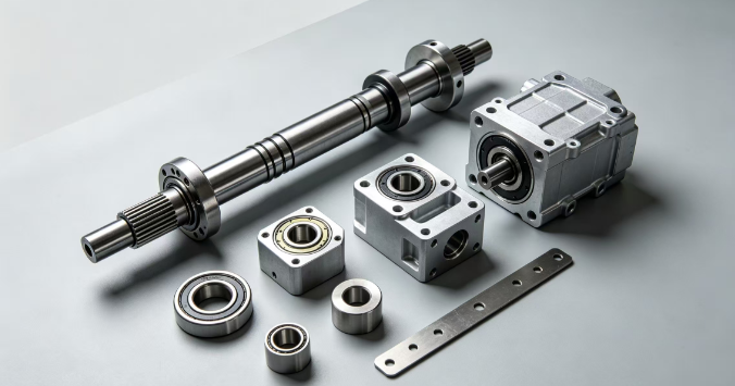
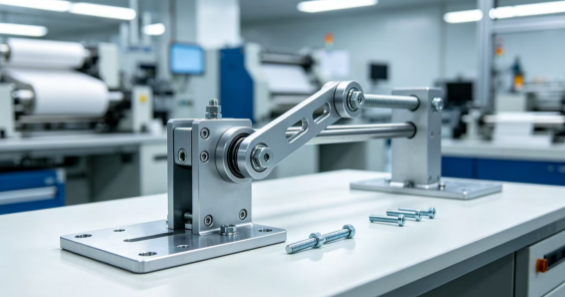
Introduction: Why Precision Components Matter in Printing and Paper Converting Machinery
Industrial printing and paper converting equipment operates through coordinated mechanical systems that feed, guide, tension, cut, fold, coat, emboss and wind continuous materials. Whether a production line manufactures labels, flexible packaging, cartons, corrugated board or commercial printed products, its performance depends on stable material movement and accurately positioned mechanical components.
A modern printing or converting line may contain feed rollers, guide rollers, tension-control assemblies, bearing blocks, cutting supports, web alignment brackets, pneumatic interfaces, mounting plates and precision shafts. These parts may not attract as much attention as the printing or cutting technology itself, but their dimensional accuracy directly affects machine alignment, repeatability, vibration, material tracking and maintenance requirements.
A small deviation in a roller diameter, bearing seat or mounting interface can influence how a web travels through the machine. Poorly positioned guide components may contribute to uneven tension or material drift. Inaccurate mounting surfaces can make equipment assembly more difficult and increase adjustment time.
CNC machining provides a flexible manufacturing solution for custom printing and paper converting machine components. Milling, turning, multi-axis machining and precision drilling can produce parts with controlled bores, mounting faces, slots, threads, shoulders and complex interfaces.
For equipment manufacturers, the objective is not simply to produce a component that matches its drawing. It is to manufacture a part that fits the assembly, performs its intended function and can be reproduced consistently.
This guide explains common machined components, material selection, critical dimensions, machining processes, surface requirements, inspection methods and cost considerations. It also outlines what engineering and purchasing teams should provide when requesting a quotation from a precision manufacturing partner.
1. Common CNC Machined Components in Printing and Paper Converting Equipment
Printing and converting machinery includes different configurations, but many systems share similar mechanical requirements. Components must support rotating elements, guide moving materials, maintain structural alignment and connect individual machine modules.
Precision rollers and roller shafts
Rollers are widely used in web handling, feeding, laminating, coating, printing and winding systems. Depending on the application, they may guide paper, film, foil, labels or other flexible materials.
A roller assembly may include a cylindrical body, shaft, bearing journals, shoulders, threaded ends, keyways and coupling features. The required geometry depends on the roller’s function and its relationship with the surrounding machine.
For example, a guide roller may require a controlled outside diameter and straightness-related characteristics. A drive roller may need additional torque-transmission features. A tension-control roller may require carefully positioned bearing interfaces and stable mounting geometry.
CNC turning is commonly used for cylindrical components. Additional milling operations can create flats, keyways, slots and mounting features.
Explore CNC turning services for cylindrical parts and precision CNC machining for components combining turned and milled features.
Bearing housings and support blocks
Bearing housings locate and support rotating shafts. Their bore dimensions, mounting faces and positional relationships influence the installation of bearings and the alignment of connected rollers.
Typical features include:
- Precision bearing bores
- Mounting holes and threaded holes
- Locating shoulders
- Flat mounting surfaces
- Counterbores and clearance pockets
- Lubrication or access features where required
A bearing housing should be designed and machined around its functional datums. If the bore must remain perpendicular to a mounting face, that relationship should be clearly identified on the drawing.
For more information about dimensional requirements, review the CNC machining tolerances guide.
Web guide brackets and alignment supports
Web guiding systems help maintain the lateral position of paper, film or other flexible materials as they pass through a production line.
Their mechanical structures may include sensor brackets, actuator mounts, guide supports, adjustment blocks and connecting plates. These parts often combine mounting holes, slots, locating faces and compact structural features.
The position of each mounting feature can influence the adjustment range and alignment of the complete assembly. A bracket that is easy to manufacture but difficult to install may increase equipment commissioning time.
CNC milling is suitable for producing these features from aluminum, steel or other appropriate materials. For complex geometries, 5-axis CNC machining can provide additional access to multiple faces and angled features.
Cutting, slitting and perforating machine components
Paper converting equipment may use rotary knives, slitting assemblies, perforating mechanisms and cutting stations. Their supporting components can include blade holders, spacers, mounting blocks, guide plates and adjustment components.
These parts may require accurate thickness, parallel faces, controlled slots and repeatable hole positions. The actual requirements depend on the cutting arrangement and the relationship between the tool and the material path.
Tool holders and precision supports should be evaluated according to operating loads, contact conditions, adjustment requirements and maintenance procedures.
Mounting plates, adapters and machine interfaces
Printing and converting lines often combine modules from different equipment designs. Custom adapters and mounting plates help connect motors, sensors, actuators, guards and mechanical assemblies.
A mounting plate may appear simple, but its hole pattern, thickness, flatness and locating features can determine whether an assembly fits correctly.
The CNC workholding fixtures guide explains how stable workholding supports repeatable machining of components with multiple functional surfaces.
2. Material Selection for Printing and Paper Converting Components
Material selection should reflect the component’s mechanical function and operating environment. Relevant factors include load, rotational speed, wear, corrosion exposure, weight, stiffness, temperature and contact with the processed material.
Choosing a material only because it is inexpensive can create problems later if the part wears quickly, deforms under load or requires additional finishing.
Aluminum alloys for lightweight machine structures
Aluminum alloys are frequently considered for brackets, mounting plates, housings, adjustment blocks and structural components.
Their relatively low density can help reduce moving mass, while CNC machining supports complex pockets, mounting patterns and precision interfaces.
However, the appropriate alloy depends on the required strength, stiffness, machinability and finishing requirements. A lightweight aluminum bracket may be suitable for a sensor mount but not necessarily for a highly loaded shaft support.
Review the aluminum material guide and broader material selection resources before finalizing a specification.
Stainless steel for corrosion and cleaning requirements
Stainless steel may be suitable for components exposed to moisture, cleaning chemicals or environments where corrosion resistance is important.
Potential applications include selected shafts, fasteners, support blocks, brackets and machine interfaces.
Different stainless grades have different corrosion resistance, strength and machining characteristics. The grade should be selected according to the actual environment rather than assuming all stainless steels perform identically.
Machining strategy should also consider work hardening, chip control, tool wear and surface finish. The stainless steel machining guide provides additional material-related considerations.
Carbon and alloy steel for loaded components
Steel may be appropriate for shafts, pins, support blocks, mounting structures and components that experience higher mechanical loads or wear.
Depending on the design, heat treatment or other secondary processes may be considered. These processes can change material properties and may affect final dimensions, so the manufacturing sequence must account for them.
For example, a turned shaft may require additional finishing after heat treatment if the drawing specifies close dimensional or surface requirements.
See the 1045 steel turned-parts guide for further considerations when manufacturing cylindrical steel components.
Engineering plastics for selected contact and guide parts
Some printing and converting systems use engineering plastics for wear strips, guide elements, spacers, protective interfaces and low-friction components.
The correct plastic depends on operating temperature, contact pressure, friction, moisture, chemical exposure and dimensional stability. Creep and deformation under sustained loading should also be considered.
Plastic components are not automatically interchangeable with metal parts. Their stiffness, thermal expansion and wear behavior may require design adjustments.
Brass and other materials for specialized interfaces
Brass and other non-ferrous materials may be appropriate for selected fittings, bushings, connectors and specialized machine interfaces.
The decision should reflect the required strength, corrosion behavior, electrical or thermal properties, machinability and mating materials.
MFG SOLUTION evaluates material choices in relation to part geometry, quantity and intended application rather than treating material selection as an isolated purchasing decision.
3. Dimensional Accuracy, Alignment and Functional Tolerances
Printing and converting machinery depends on coordinated movement. A component’s individual dimensions matter, but the relationships between features can be even more important.
Define the functional datum system
A datum system should reflect how the part is located and assembled in the actual machine.
For a bearing support, the mounting face may act as a primary reference, while the bearing bore establishes the shaft position. For a guide bracket, a locating edge and mounting-hole pattern may determine the installed position.
If the drawing does not clearly identify these references, the manufacturer may need to make assumptions about how dimensions should be controlled.
The guide to CNC part geometry optimization can help engineering teams consider functional geometry and manufacturability before production.
Control bearing bores and shaft interfaces
Bearing bores and shaft journals should be specified according to the selected bearing, loading conditions and assembly arrangement.
The required fit may differ depending on which bearing ring rotates relative to the load and how the assembly is supported.
Avoid assigning extremely tight tolerances to every diameter without a functional reason. Instead, identify the interfaces that determine bearing location, rotation and assembly performance.
Manage hole position and mounting accuracy
Mounting holes connect machine components and establish their installed positions. Their diameter, position, thread quality and relationship to reference faces may all be important.
For a component with several hole patterns, the drawing should make clear which features share a common datum system.
The CNC hole tolerance guide explains when drilling is sufficient and when reaming or boring may be more suitable.
Avoid unnecessary tolerance accumulation
A roller assembly may include a shaft, two bearing housings, spacers, mounting plates and a drive interface. Each component contributes some dimensional variation.
If every individual dimension is tightened without considering the complete assembly, production cost may increase without delivering a meaningful improvement.
Engineering teams should identify the final functional requirement and determine which dimensions control it. This approach helps manufacturers allocate machining and inspection effort more effectively.
For additional guidance, see why CNC machining tolerance affects part price.
4. Selecting CNC Processes for Printing Machinery Parts
Different components require different manufacturing routes. A suitable process depends on geometry, material, tolerance, quantity, surface requirements and production schedule.
CNC milling for brackets, plates and housings
CNC milling is commonly used for rectangular, prismatic and multi-feature components.
Typical applications include:
- Bearing support blocks
- Web guide brackets
- Mounting plates
- Sensor holders
- Adjustment blocks
- Cutter supports
- Adapter housings
Milling can produce pockets, slots, threaded holes, counterbores, flat surfaces and locating features. The number of setups depends on how many faces require machining and how the component can be held securely.
Where multiple features must maintain close positional relationships, a process plan that minimizes unnecessary repositioning may improve consistency.
CNC turning for rollers, shafts and spacers
CNC turning is suitable for components dominated by cylindrical geometry.
It can produce roller shafts, bearing journals, spacers, sleeves, pins, shoulders and grooves. Additional operations may be required for keyways, cross-holes, flats or other non-rotational features.
The machining sequence should consider the relationship between bearing seats, shoulders, threads and coupling interfaces.
5-axis machining for complex interfaces
Some machine components have angled faces, intersecting features or geometry that is difficult to access using conventional setups.
Five-axis machining can reduce repositioning for suitable components and provide access to multiple surfaces. It is particularly useful when several features must maintain controlled spatial relationships.
However, five-axis machining is not automatically the most economical choice. Simpler three-axis or four-axis strategies may be more appropriate for less complex parts.
The manufacturing route should be selected based on the actual drawing and production requirements.
Swiss turning for small precision components
Printing machinery may contain small pins, shafts, bushings, spacers and specialized fittings.
For long, slender or feature-dense components, Swiss-type turning may be worth evaluating. The process can support efficient production of suitable small-diameter parts.
Its suitability depends on part dimensions, geometry, material and order quantity. Learn more about Swiss turning for small precision parts.
Workholding and setup planning
Thin plates, long shafts and irregular housings create different workholding challenges.
Insufficient support can cause vibration, distortion or dimensional variation. Excessive clamping force can also deform thin-walled parts.
Workholding should therefore be designed around the component’s geometry, material and critical features. For repeat production, dedicated fixtures may improve setup consistency and reduce handling time.
5. Surface Finish, Deburring and Wear Considerations
Surface finish should be specified according to the function of each surface.
A bearing seat, roller contact surface, mounting face and protective cover do not necessarily need the same finish. Applying a demanding surface requirement to every face can increase cost without improving machine performance.
Functional surfaces
Roller surfaces may influence contact with the processed web. Bearing seats affect bearing installation, while mounting faces support stable assembly.
Where surface finish has a functional purpose, the drawing should identify the relevant area and requirement.
The CNC machining surface finish guide explains how surface texture relates to manufacturing processes and application requirements.
Deburring and edge quality
Machined parts may contain sharp edges, burrs and small raised material around holes or slots.
Burrs can interfere with assembly, damage adjacent components or create handling risks. Internal intersections and cross-holes may require particular attention because they can be difficult to access.
The drawing should distinguish between edges requiring a defined radius or chamfer and edges that only need general deburring.
Surface treatment and dimensional effects
Depending on the material and operating environment, components may require anodizing, plating, passivation, coating or another surface treatment.
The selected treatment should be compatible with the material and the part’s function. It may also affect dimensions, particularly on close-fit interfaces.
Bearing seats, threads, locating diameters and precision bores may need masking, post-treatment machining or another planned approach.
Review surface finishing options for CNC machined parts before specifying secondary operations.
6. Quality Inspection for Printing and Converting Machine Components
Inspection should verify the dimensions and characteristics that determine part function and customer acceptance.
A useful inspection plan starts with the drawing, material requirements, purchase order and agreed quality documentation.
Dimensional inspection
Depending on component geometry, inspection may include:
- Outside and inside diameters
- Bearing bore dimensions
- Shaft journal dimensions
- Hole diameter and position
- Overall length and thickness
- Flatness and parallelism
- Perpendicularity and other specified geometric controls
- Thread dimensions
- Surface condition
Measurement methods should be appropriate for the feature and tolerance. Calipers may be suitable for general dimensions, while micrometers, bore gauges, height gauges, coordinate measuring machines or other instruments may be needed for tighter requirements.
First-article and in-process inspection
First-article inspection can confirm that the initial production parts meet the agreed drawing requirements.
During production, selected dimensions may be checked at defined intervals. The frequency should reflect process stability, quantity, complexity and the consequences of a nonconforming part.
For example, a long roller shaft with multiple bearing journals may require checks at several points along its length. A mounting bracket may need verification of its hole pattern and reference faces.
Material and process documentation
Some projects require material certificates, treatment records, inspection reports or batch identification.
The required documents should be agreed before production begins. This avoids uncertainty about what must be recorded and supplied with the shipment.
MFG SOLUTION supports quality planning through its manufacturing capabilities and established inspection processes. For a broader overview, see quality assurance standards for CNC machining parts and the ISO 9001 precision machining guide.
Packaging and shipment protection
Precision components can be damaged after inspection if they are not packaged appropriately.
Roller shafts may require protection against impact and corrosion. Finished mounting faces should be protected from scratches, while small parts should be packed to prevent loss or surface damage.
Packaging requirements should consider part size, weight, surface treatment, shipping distance and the customer’s receiving process.
7. Cost Control and Manufacturing Efficiency
The lowest unit price does not always represent the lowest total procurement cost. A component that is inexpensive to machine but difficult to assemble, inspect or maintain may create additional costs throughout the equipment lifecycle.
Design for manufacturability
Manufacturability reviews can identify features that increase machining time without adding functional value.
Examples include unnecessarily deep pockets, inaccessible internal corners, excessive thread depth, overly complex setups and tight tolerances on noncritical surfaces.
Design teams should review tool access, material removal, wall thickness and workholding before releasing the drawing.
Match process to production quantity
Prototype, small-batch and repeat-production orders may require different manufacturing strategies.
For prototypes, flexible CNC machining can support design validation without requiring dedicated production tooling. For recurring orders, fixtures and documented processes may reduce setup variation.
For higher quantities, automatic turning, cold forging or other processes may be worth comparing when the component geometry allows.
The CNC machining cost analysis guide explains the factors that influence machining cost. It is also useful to understand how to reduce machining costs without sacrificing quality.
Avoid over-specification
Tight tolerances, premium materials and extensive finishing operations should be specified where they serve a real functional purpose.
A good drawing separates critical interfaces from general dimensions. This helps the manufacturer choose an economical process while maintaining the required performance.
Consider total project requirements
A complete manufacturing quotation may involve material, machining, secondary operations, inspection, packaging and delivery.
Comparing quotations only by unit price can hide differences in scope. Purchasing teams should confirm whether all suppliers are quoting the same material, tolerances, finishing, inspection and documentation requirements.
8. How to Prepare an RFQ for Custom Printing Machinery Components
A clear request for quotation helps reduce engineering questions and improves the accuracy of supplier responses.
Whenever possible, provide:
- 2D engineering drawings: Include dimensions, tolerances, datums, surface requirements and revision information.
- 3D CAD files: STEP or another mutually accepted format helps clarify complex geometry.
- Material specification: Identify the required grade or ask the manufacturer to recommend suitable alternatives.
- Order quantity: State prototype quantity, initial production quantity and expected repeat demand if known.
- Surface treatment: Specify anodizing, plating, coating, polishing or other required finishing.
- Inspection requirements: Identify critical dimensions and any required inspection reports.
- Application information: Explain whether the part supports a roller, bearing, web guide, cutter or other machine assembly.
- Delivery expectations: Include the required delivery schedule and destination.
- Packaging requirements: Explain whether parts need individual protection, corrosion prevention or special identification.
If the drawing is still under development, send the available geometry and describe the unresolved requirements. A manufacturing review may identify design changes before the final specification is released.
You can start through the MFG SOLUTION online quotation page or contact the team through the MFG SOLUTION contact page.
9. Why Work With a Precision Manufacturing Partner?
Printing and paper converting equipment manufacturers often need a combination of custom machined parts rather than one standardized component.
A project may involve turned shafts, milled brackets, bearing housings, mounting plates, small precision fittings and engineering plastic parts. Coordinating these components requires an understanding of geometry, material, tolerances, secondary operations and inspection.
MFG SOLUTION provides manufacturing support across CNC machining, CNC turning, five-axis machining, Swiss turning and related production processes. The manufacturing route is evaluated according to part requirements rather than forcing every component into the same process.
For engineering teams, this can help simplify supplier coordination and provide a clearer path from prototype evaluation to repeat production.
The most effective cooperation begins with accurate drawings, clear functional requirements and early communication about critical features.
Frequently Asked Questions
1. What printing machine components can be manufactured by CNC machining?
Common examples include roller shafts, bearing housings, web guide brackets, mounting plates, sensor supports, cutter holders, spacers, adapters and precision machine interfaces. The appropriate process depends on part geometry, material, tolerance and quantity.
2. Which materials are suitable for printing and paper converting machinery?
Aluminum, stainless steel, carbon steel, alloy steel, brass and selected engineering plastics may be suitable. Material selection should consider load, wear, corrosion exposure, stiffness, weight, temperature and contact conditions.
3. Is CNC turning suitable for roller shafts?
Yes. CNC turning is commonly used for cylindrical roller shafts, bearing journals, shoulders, grooves and threaded features. Additional milling or drilling may be needed for keyways, flats and cross-holes.
4. How should bearing housing tolerances be specified?
Specify the functional bore dimensions, mounting relationships and relevant geometric tolerances according to the bearing and assembly requirements. The drawing should clearly identify datums and distinguish critical interfaces from noncritical surfaces.
5. Can MFG SOLUTION manufacture prototype and low-volume machine parts?
CNC machining is suitable for prototypes and low-to-medium volume components because it supports design changes without requiring dedicated tooling for every part. The most appropriate process depends on geometry, material and quantity.
6. Do machined printing machine components require surface treatment?
Not always. Some components can be used in their machined condition, while others may require anodizing, plating, passivation or coating. Treatment should be selected according to corrosion, wear, appearance and dimensional requirements.
7. What files are needed for a CNC machining quotation?
A 2D drawing and 3D CAD file are preferred. Include material, quantity, tolerances, surface finish, secondary operations, inspection requirements and delivery expectations whenever available.
8. How can manufacturers reduce the cost of custom printing machinery components?
Review the design for manufacturability, avoid unnecessary tight tolerances, select suitable materials, reduce avoidable machining setups and match the production process to order quantity. Early engineering communication can prevent expensive changes later.
Request a Quote for Custom Printing and Paper Converting Machine Components
Reliable printing and paper converting equipment depends on mechanical components that fit accurately, maintain alignment and perform consistently throughout production.
Whether you need precision roller shafts, bearing housings, web guide brackets, cutter supports, mounting plates or other custom machine components, MFG SOLUTION can review your drawings and evaluate suitable manufacturing processes.
Send your 2D drawings, 3D CAD files, material requirements and order quantity for an engineering review.
Request a quotation: https://mfg-solution.com/online-quote/
Contact MFG SOLUTION: https://mfg-solution.com/contact-mfg-solution/
Learn more about our CNC machining services, CNC turning capabilities and manufacturing capabilities to discuss your next precision component project.