
2026-10-12
Why Design for Manufacturability Saves Money Before Day One

Understanding what is design for manufacturability is essential. Design for Manufacturability (DFM) is the practice of shaping a part’s geometry, tolerances, and material choices during the design phase so it can be machined efficiently, without costly rework or delays. For precision machining, that means fewer setups, standard tool sizes, achievable tolerances, and material that’s readily available. Applied early, DFM cuts cost and lead time before a single chip is cut, because changes made on a CAD screen are free compared to changes made after tooling or fixturing is built.
What Is Design for Manufacturability and Why Does It Matter for Precision Machining?
For precision machining, manufacturability means a part’s geometry, tolerances, material, and finish all match what a standard CNC setup can produce without special tooling or fixturing. Answering what is design for manufacturability in this context starts with one idea: a well-machined part is one that was designed to be machined, not just designed to function.
What Does Manufacturability Mean in the Context of Precision Machined Parts?
A manufacturable machined part uses features a Swiss lathe, CNC turning center, or mill-turn machine can produce in a standard setup, not one that demands a custom fixture or a one-off tool. That includes tolerances held only where the part actually needs them, wall thicknesses that survive clamping and cutting forces, and materials that are stocked and machinable rather than exotic alloys ordered for one job. Wikipedia’s engineering definition of design for manufacturability describes it as reducing manufacturing cost and difficulty by accounting for raw material type, material form, dimensional tolerances, and secondary finishing early in the design. For a shop running batch production of parts up to 38mm in diameter, that alignment between design and machine capability is what separates a quote that ships on schedule from one that stalls in engineering review.
How Does Design for Manufacturability Reduce Production Costs and Turnaround Times?
The mechanism is timing: a dimension changed on a CAD model costs nothing, but the same change discovered after quoting or first article inspection means re-tooling, re-quoting, and a schedule slip. Industry estimates commonly cited in DFM literature put 70-80% of a product’s total cost as locked in during the design phase, before a single part is cut. That is why catching a problem on screen is cheap and catching it on the shop floor is not.
Unnecessary tight tolerances, deep pockets, and thin walls are the usual culprits. A tolerance tightened out of habit rather than function forces slower feeds, more inspection, and sometimes a secondary grinding or EDM operation. Deep pockets and thin walls increase tool deflection and vibration, which drives extra roughing passes, longer cycle times, and higher scrap rates when walls distort or chatter marks fail inspection.
Turnaround depends on this review happening before the quote, not after. MFG SOLUTION’s engineering team evaluates part geometry, tolerances, and material against its CNC turning, Swiss lathe, cold forging, automatic lathe, and mill-turn capabilities during the 8-hour quoting window, so a design that passes manufacturability review moves straight to production without an engineering hold. That early check is also what makes a 3-day shipment window realistic once an order is approved.
What Are the Core Principles and Best Practices of Design for Manufacturability?
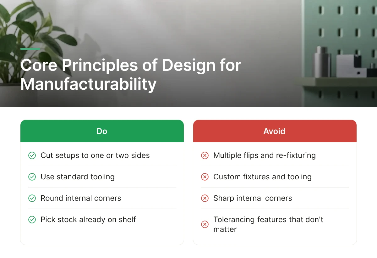
The core principles of design for manufacturability come down to five habits: cut setups, use standard tooling, round internal corners, tolerance only what matters, and pick stock that’s already on the shelf.
Each one maps directly to a line item on a machinist’s quote. Violate one and the quote goes up, the lead time stretches, or both.
Minimize Setups and Use Standard Tooling
Every time a part has to be removed from the machine, re-fixtured, and re-indicated, you add time and introduce a new source of error. A part designed so its features are accessible from one or two sides, rather than requiring a flip to a third or fourth orientation, cuts cycle time and reduces the chance of misalignment between features.
Standard tool diameters and thread sizes matter for the same reason. A hole sized for a stock 3.2mm drill costs less to produce than one that forces a shop to order a custom reamer. The same logic applies to threads: stick to common metric or UN series sizes unless the application genuinely requires something else.
Avoid Sharp Internal Corners
Cutting tools are round. A sharp 90-degree internal corner on a drawing has to be approximated with a radius or produced with slower, specialized tooling like an EDM operation. Specifying a radius that matches a standard end mill, rather than leaving the corner sharp on paper, keeps the part machinable with standard cutters and avoids a secondary process.
Apply Tolerances Strategically
Tight tolerances should apply only to the features that function requires, a bearing bore, a mating thread, a sealing diameter. Everywhere else, generous tolerances cut inspection time and scrap because the machine doesn’t have to chase a number it doesn’t need to hit. Since up to 70-80% of a product’s total cost gets locked in during the design phase, tolerance decisions made on the drawing have outsized downstream effects on cost and rework.
Choose Available Materials
Specifying a readily available stock size and standard material grade avoids special-order delays and the machining surprises that come with unfamiliar alloys. A bar stock diameter that’s one size off from standard can add weeks to a lead time before the first chip is cut.
What Are the Most Common Design for Manufacturability Mistakes Engineers Should Avoid?
The most common mistakes are over-tolerancing an entire drawing, specifying deep thin-walled pockets, designing chip traps, and ignoring fixture access.
- Over-tolerancing everything: Applying ±0.01mm across every dimension forces 100% inspection and drives scrap rates up for no functional benefit.
- Deep, thin-walled pockets: These flex under cutting pressure, chatter, and often fail to hold tolerance regardless of machine quality.
- Features that trap coolant or chips: Blind pockets with no clearance path collect debris, slow cycle time, and complicate cleaning before shipment.
- Ignoring fixture access: A feature that’s geometrically possible to cut but impossible to clamp still isn’t manufacturable.
How Does Design for Manufacturability Apply Differently to Small Precision Parts Versus Larger Assemblies?
Small precision parts live or die on tolerance stacking and tool access; larger assemblies hinge more on fixturing, material removal volume, and handling.
On a part under 38mm in diameter, the range MFG SOLUTION machines on Swiss lathes and CNC turning centers, a few microns of tolerance stack-up between features can mean the difference between a part that assembles and one that doesn’t, and tool access into tight bores becomes the binding constraint. On a larger weldment or housing, the bigger cost drivers shift to how much material gets removed, how the part sits in a fixture across multiple operations, and how it’s handled without damage between steps. What is design for manufacturability for a 10mm pin is a different conversation than for a 300mm bracket, even though the underlying principles, fewer setups, standard tooling, strategic tolerancing, stay the same.
How Do You Implement Design for Manufacturability in Your Product Development Process?
You implement design for manufacturability by inserting manufacturing feedback at five checkpoints, sketch, early review, prototype quote, revision, and final release, instead of one review at the end.
Answering what is design for manufacturability in practice means treating it as a loop, not a gate. Each pass through that loop should cost less time than the last, because the design converges toward something a machine shop can run without guesswork.
What Does a Step-by-Step Design for Manufacturability Process Look Like From Design to Production?
Start with a concept sketch or rough CAD model that captures function, not final tolerances. Before locking geometry, send it to a machinist or applications engineer for an early manufacturability review, this is the step most teams skip, and it’s the one that catches problems a design-only review can’t, because engineers reviewing their own CAD tend to evaluate function and fit, not machinability.
A machinist looks at the part differently: can this wall thickness survive turning without chatter, does this internal corner need an EDM operation, will this tolerance require secondary grinding. Someone who runs CNC turning, Swiss lathe, or cold forging equipment daily spots these issues in minutes because they’ve cut the mistake before.
Next, submit the revised design for a prototype quote. At MFG SOLUTION, that quote comes back within 8 hours, fast enough to treat quoting as a design tool rather than a procurement step. Use the quote feedback to revise: if a feature drives cost or lead time disproportionately, change it before tooling or fixtures get built around it. Repeat the review-quote-revise cycle until the design stabilizes, then release final drawings for production.
What Measurable Results and ROI Can You Expect From Implementing Design for Manufacturability?
The clearest signal that DFM worked is quoting behavior itself. If quotes across successive design iterations come back fast and land in a similar cost range, the design has reached a stable, producible state. If each revision triggers a new round of clarifying questions or wildly different pricing, the geometry still has manufacturability problems hiding in it.
Downstream, track three outcomes qualitatively rather than chasing a single invented percentage: fewer engineering change orders issued after drawing release, fewer first-article parts rejected at incoming inspection, and a shorter gap between design freeze and first shipment. Because up to 70-80% of a product’s total cost gets locked in during the design phase, small corrections made before release avoid expensive rework later, redesigns, scrapped tooling, missed launch dates.
This process scales without changing structure. A single prototype order follows the same five steps as a 10,000-unit repeat run; the difference is that repeat orders carry a known cost and quality baseline from the first cycle, which is why manufacturers running parts under 38mm through CNC mill & turn or automatic lathe production under ISO 9001:2015 and IATF 16949 process control find each subsequent batch faster to quote and ship than the first.
What’s the Difference Between DFM, DFA, and DFMA?
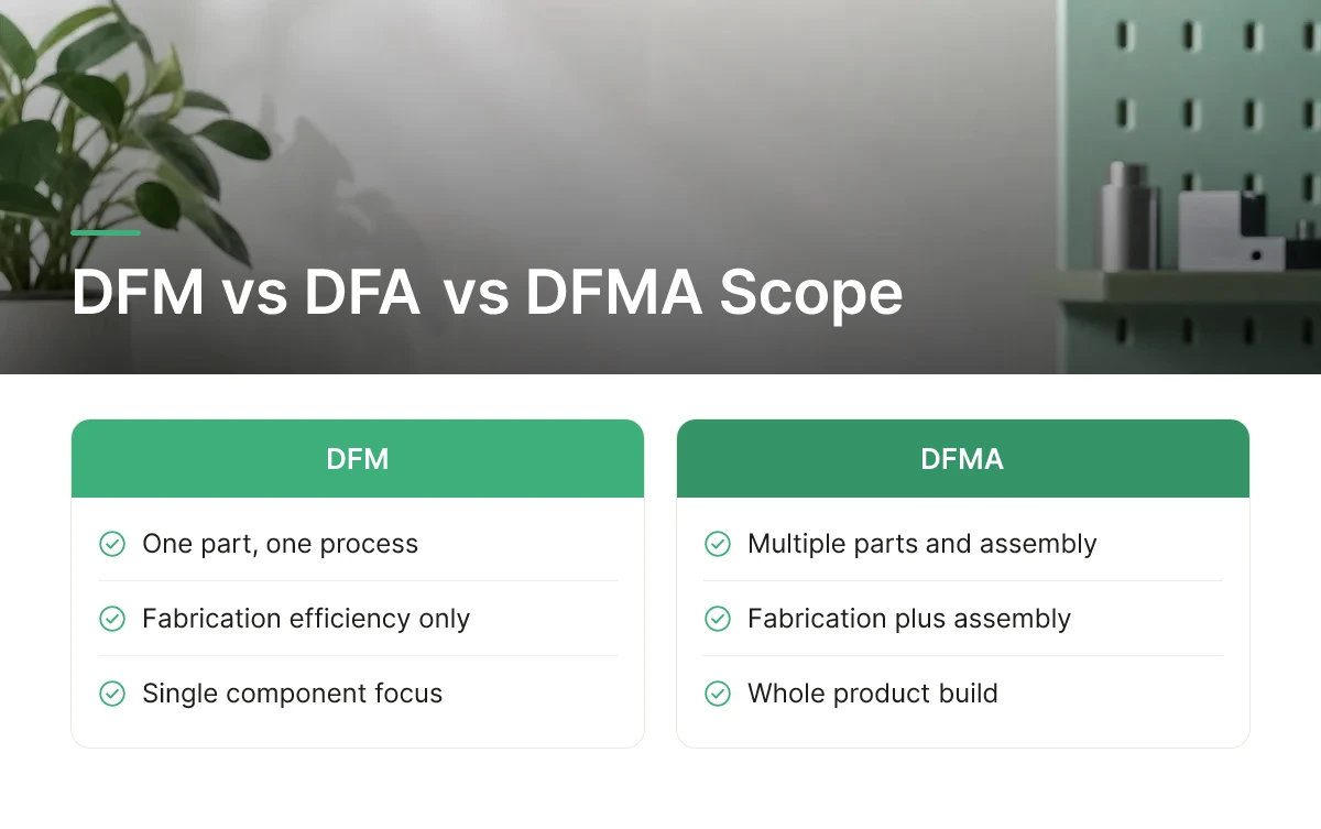
DFM optimizes a single part for fabrication, DFA optimizes how multiple parts fit together, and DFMA combines both across the whole product build.
These three terms get used interchangeably in casual conversation, but they describe different scopes of work. Knowing which one applies to your project saves engineering time and keeps feedback from your machining partner focused on the right questions.
Design for Manufacturing (DFM): One Part, One Process
DFM asks a narrow question: can this specific part be fabricated efficiently with the process you’ve chosen? For a precision machined component, that means evaluating wall thickness, tolerance stack-up, tool access, and material removal against CNC turning, Swiss lathe, cold forging, or mill-turn capabilities. The scope stays contained to a single part’s geometry and the machine that cuts it.
Design for Assembly (DFA): Multiple Parts, One Build
DFA shifts the lens from the part to the product. It asks how many parts you actually need, whether fasteners can be eliminated, and how much labor or robotic time each assembly step adds. Reducing part count is usually the biggest lever here, fewer unique components mean fewer interfaces that can misalign, fewer purchase orders, and less inspection overhead.
DFMA: The Combined Discipline
DFMA merges both lenses into one workflow, running from individual part fabrication through final assembly of the finished product. A DFMA review looks at whether each part is easy to machine AND whether the full set of parts assembles with minimal steps, tooling changes, and rework. This combined view is standard practice for products with multiple subcomponents, brackets, housings, fasteners, and machined inserts that all have to come together on a line.
When Should You Use DFM Versus DFA or DFMA for Your Precision Machining Projects?
Use DFM alone when you’re ordering a single machined component that ships as-is, with no downstream assembly on your end. If you’re sourcing a precision shaft, pin, or fitting up to 38mm in diameter as a standalone part, the questions that matter are about tolerances, material, and machining cost, not how it mates with six other pieces.
Switch to DFA or full DFMA thinking once that part becomes one of several being assembled into a finished product. At that point, the design conversation has to include fit, fastening method, and assembly sequence, not just the machinability of the one component. This is also where understanding what is design for manufacturability pays off early: knowing which lens to apply before you finalize drawings prevents rework after tooling is already cut.
What Tools and Software Can Help You Apply Design for Manufacturability to CNC Parts?
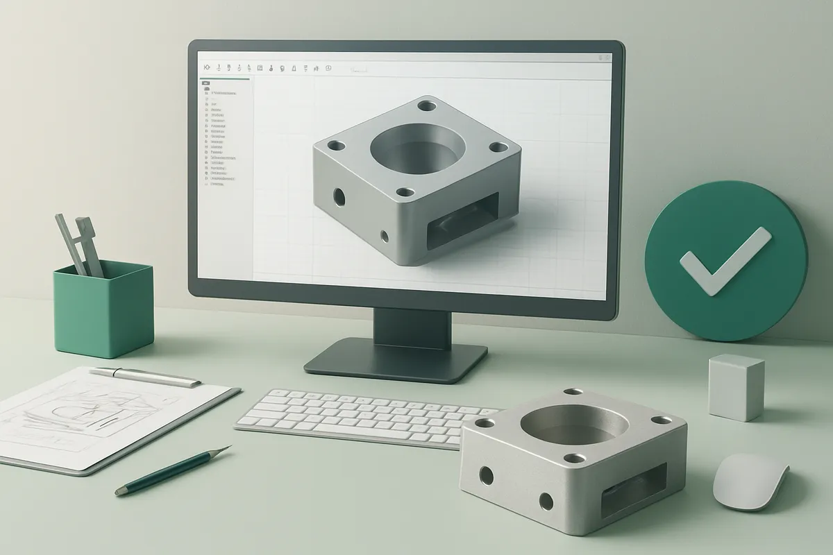
CAD-integrated DFM checkers, instant online quoting engines, and CAM simulation software let engineers catch manufacturability problems before a design ever reaches a machine shop.
How Do CAD Systems and Manufacturing Software Integrate With Design for Manufacturability Workflows?
Most mid-range and premium CAD platforms now include manufacturability add-ins that scan a solid model for thin walls, deep pockets a cutting tool can’t reach, and tolerance callouts that conflict with the chosen material or process. These checks run inside the design environment, so an engineer sees the flag before exporting a file, not after a quote comes back high or late. This is the practical answer to what is design for manufacturability at the tooling level: software that enforces process limits while the part is still a sketch, not a shipped drawing.
Instant online quoting tools serve a second, less obvious function as manufacturability checks. If an automated quoting system can’t price a part, or returns a quote with unexplained cost spikes, that’s often a signal the geometry has a problem: a wall too thin for the material, a feature beyond standard tolerance bands, or a diameter outside the shop’s capacity. MFG SOLUTION’s 8-hour quoting process works this way in practice: specifications that trigger manual review or delayed turnaround usually point to a manufacturability issue worth revisiting before committing to a production run.
CAM software adds a third layer by simulating the actual toolpath. Running a design through CAM simulation before cutting confirms that a tool can physically reach every called-out feature and that estimated cycle times line up with what the design intended, catching cases where a feature looks fine on screen but forces excessive tool changes or slow feed rates on the shop floor.
File format and model-based definition (MBD) practices matter more than they get credit for. Translating a design between CAD systems, STEP, IGES, or native formats, can introduce rounding errors or drop annotations, creating mismatches between what the designer specified and what the machinist sees. MBD embeds tolerances and notes directly in the 3D model, cutting that translation risk.
None of these tools replace a trained eye on complex parts. They’re a pre-quote filter, useful for catching obvious issues fast, but a manufacturing engineer should still review tight-tolerance or multi-process parts before they go into production.
Frequently Asked Questions
Does Design for Manufacturability only apply to new designs, or can existing parts be redesigned for it?
Both, DFM applies to new designs and existing parts already in production. Legacy parts often carry unnecessary tolerances, excess material, or outdated tooling choices that a DFM review can flag. Revisiting a mature part’s geometry or process selection frequently uncovers cost savings that were never addressed at launch, especially if the original design predates current machining capabilities.
Who should be involved in a Design for Manufacturability review?
A DFM review needs design engineers, manufacturing engineers, and quality staff in the same conversation, not separate handoffs. Procurement should weigh in on material and supplier constraints, and a machining partner’s process engineers add insight into what’s actually efficient to produce. Skipping any one group tends to reintroduce the problems DFM is meant to catch.
How early should Design for Manufacturability be considered in a project timeline?
Start DFM during initial concept sketches, before tolerances and materials get locked in. Up to 70-80% of a product’s total cost gets determined during the design phase, so waiting until drawings are finalized limits how much cost and complexity can actually be removed. Early involvement costs little; late changes cost tooling, schedule, and rework.
Does applying Design for Manufacturability limit design creativity or part complexity?
No, DFM redirects complexity toward what adds function, not what adds cost without benefit. A part can still be intricate if that complexity serves performance; DFM simply questions tolerances, features, or geometries that exist by habit rather than necessity. Many engineers find DFM sharpens design decisions rather than restricting them.
Conclusion
Design for manufacturability works best as a discipline applied early, revisited often, and shared across design, manufacturing, and quality teams. The parts that ship fastest and cheapest are usually the ones where tolerances, materials, and geometry were questioned before drawings were finalized, not after a quote came back too high.
If you’re sitting on a drawing that hasn’t been reviewed for manufacturability, send it to MFG SOLUTION for a quote within 8 hours. Our engineering team will flag tolerance, geometry, or process choices worth revisiting before you commit to a production run.
Recommended Articles
Explore more from our content library: