
2026-09-15
Optimize CNC Hole Drilling for Fast, Accurate Small Parts

Understanding CNC hole drilling optimization is essential. You optimize CNC hole drilling for small precision parts by matching drill method, feed rate, and coolant delivery to hole depth-to-diameter ratio and material, not by pushing speed alone. For holes under 38mm, the biggest cycle-time gains come from cutting vibration and runout at the entry point, since a poor entry causes drift, breakage, and rework that costs far more time than a slower feed. Balancing accuracy and speed means matching tooling and setup to the specific hole geometry before adjusting spindle parameters.

Assess Your Hole Requirements Before You Set Up
Before adjusting a single feed rate, answer four questions: how deep is the hole relative to its diameter, what material and chip type are you cutting, what entry condition does the surface present, and what tolerance must the finished hole hold. These answers determine the drilling method, CNC hole drilling optimization starts on paper, not at the spindle.
How Hole Depth, Diameter, and Material Change Your Drilling Strategy
Diameter alone tells you almost nothing about difficulty. The depth-to-diameter ratio is what decides whether a standard twist drill and a single peck cycle will finish the job, or whether you need a deep-hole method built for chip evacuation and straightness over long, narrow passages. A common industry threshold treats a hole as “deep” once depth reaches roughly 10 times the diameter, and past that point drift, poor finish, and tool failure become far more likely without a dedicated approach.
- Calculate the depth-to-diameter ratio first, it dictates tool selection more than raw hole size does.
- Identify the material and its chip behavior: stringy chips from softer alloys pack differently than the brittle, fractured chips typical of cast or hardened materials.
- Match peck depth and retraction frequency to that chip type, stringy chips need more frequent retractions to clear the flute; brittle chips often clear on their own with a longer peck interval.
Why Entry Geometry and Chip Control Matter for Cycle Time
A clean, centered entry prevents drill walk, and preventing walk is what actually shortens cycle time, not a faster feed rate. Spotting the hole or machining a pilot at a controlled entry angle keeps the drill from deflecting off an uneven or angled surface, which otherwise forces a re-cut, a broken tool, or a scrapped part. Every re-cut adds setup and machine time that dwarfs whatever seconds a shop saved by skipping the spot drill step.
For parts up to 38mm in diameter, the range MFG SOLUTION machines across CNC turning, Swiss lathe, and mill-turn processes, tolerance and surface finish requirements often narrow the viable method list before cost enters the conversation at all. A hole with a tight positional tolerance or a fine finish callout may rule out standard drilling entirely, pointing instead toward boring, reaming, or a combined drill-and-ream sequence. Getting this assessment right up front is what separates a controlled, repeatable process from one that depends on operator judgment at every batch.
Choose the Right Drilling Method for CNC Hole Drilling Optimization
The right method depends on depth-to-diameter ratio and part size: standard drilling for shallow holes, gundrilling for deep small-diameter precision work, BTA for larger deep bores. Getting this choice wrong is the single biggest driver of wasted cycle time and scrapped tools on small precision parts.
Most CNC hole drilling optimization decisions come down to one number: how deep is the hole relative to its diameter. A hole with a depth-to-diameter ratio under roughly 5:1 is straightforward territory for a standard twist drill or spot-and-peck cycle on a mill or lathe. Push past that ratio, common in fuel system components, medical instrument shafts, and connector housings, and standard drilling starts to lose straightness, forcing a switch to gundrilling or BTA (Boring and Trepanning Association) drilling.
Cost and Speed Trade-Offs Between Gundrilling, BTA, and Standard Drilling
Standard drilling wins on setup simplicity and per-part cost for shallow holes, no special coolant-through tooling, no dedicated deep-hole machine, and tool changes are cheap. Gundrilling trades feed rate for straightness and surface finish: a single-flute gundrill runs slower than a standard twist drill, but it holds tolerance over long depths that a conventional drill cannot reach without walking off center. BTA drilling favors faster stock removal on larger bores because its tooling supports higher feed and coolant flow through a larger cross-section, making it efficient on diameters where gundrilling would be too slow to justify the cycle time.
When to Use Each Method Based on Hole Depth and Precision
Standard drilling breaks down once the depth-to-diameter ratio climbs high enough that the drill deflects or the flutes can no longer clear chips reliably, packed chips and heat buildup are usually the first signs. Gundrilling depends on oil-based coolant delivered under pressure through the tool to flush chips and control heat, which means shops need dedicated equipment and fluid handling, not just a modified spindle. BTA drilling has a practical lower diameter limit, the tooling geometry needs enough cross-section for the boring bar and chip-return channel, so it doesn’t scale down to small precision bores.
For parts up to 38mm in diameter, most holes fall into standard drilling or gundrilling territory rather than BTA, which is built for larger-bore, heavy-stock-removal work. At MFG SOLUTION, matching the drilling method to part geometry, rather than defaulting to whatever tooling is already set up, is part of how quotes get returned within 8 hours without sacrificing hole straightness or finish on delivery.
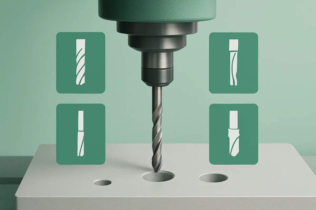
Set Up Tooling to Reduce Runout, Vibration, and Tool Breakage
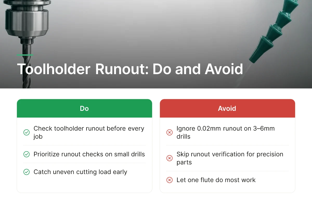
Toolholder runout is the single most preventable cause of broken drills and out-of-tolerance holes in small-part machining, and checking it before every job costs minutes but saves tools. On a 3mm or 6mm drill, even 0.02mm of runout at the holder shifts the cutting load unevenly across the flutes, so one edge does most of the work while the other rubs instead of cutting. That imbalance shows up as premature edge wear, oversized holes, or a snapped drill halfway through a batch. The smaller the diameter, the less runout the tool can tolerate before the effect compounds, a rule that makes runout checks non-negotiable for parts machined at 38mm and under, where tolerances are already tight and margin for error is thin.
Tool Choices That Perform Best on Small-Diameter Precision Holes
Rigid setup starts with keeping tool overhang as short as the part geometry allows, since every extra millimeter of stickout multiplies deflection and lets vibration build. Matching the toolholder to the tolerance requirement matters just as much as the drill itself.
- Standard collet holders handle roughing operations and looser-tolerance holes at a budget-friendly cost, but their runout typically runs higher than precision alternatives.
- Shrink-fit holders grip the tool shank uniformly around its full circumference, cutting runout significantly and holding well under high-speed drilling.
- Hydraulic holders dampen vibration through internal fluid pressure, which helps on longer engagements or harder alloys where chatter is the bigger risk.
The right choice depends on what the part demands. A medical component with a sub-0.01mm positional tolerance justifies premium hydraulic or shrink-fit tooling; a commodity bracket with generous hole tolerance rarely needs it. This is the core trade-off in CNC hole drilling optimization, matching tooling investment to the tolerance actually specified, not over- or under-building the setup.
How to Diagnose Runout, Vibration, and Premature Tool Failure
Runout, vibration, and programming error produce overlapping symptoms, but each has a distinct signature and a different fix.
- Runout shows as an oversized or bell-mouthed hole with uneven wear on one cutting edge, measure it with a dial indicator on the tool shank before cutting, not after a part fails inspection.
- Vibration or chatter leaves visible chatter marks on the hole wall and a distinct audible tone change during the cut, the fix is usually shorter overhang, a stiffer holder, or reduced spindle speed, not a new drill.
- Programming error, wrong feed rate, missed peck cycle, or incorrect retract height, tends to produce consistent failures across every part in the run, unlike runout or vibration, which worsen gradually as a specific tool wears.
Separating these causes before adjusting anything prevents shops from replacing a good tool when the real problem is a program parameter, or reprogramming a job when the holder simply needs replacing.
Configure Feed Rate, Spindle Speed, and Coolant Delivery
Feed, speed, and coolant settings determine whether a hole finishes on spec in one pass or drifts, work-hardens, or clogs with chips, the core mechanics behind CNC hole drilling optimization for parts under 38mm.
Adjusting Feed Rates and Spindle Speeds for Different Materials and Depths
Set spindle speed first by material family, then adjust feed rate against hole depth rather than treating the two as independent variables. Softer, more ductile metals like aluminum and brass tolerate higher spindle speeds but generate long, stringy chips that need faster feed to break cleanly. Harder alloys, stainless, titanium, hardened tool steel, need lower speeds to limit heat buildup at the cutting edge, paired with a feed rate conservative enough to avoid work hardening the hole wall on withdrawal.
- Start from the material’s known machinability range, then step speed down as hole depth-to-diameter ratio increases, since heat and deflection compound the deeper the drill travels.
- Reduce feed rate incrementally as depth increases rather than holding a constant feed from entry to bottom, a rate that works cleanly at the surface often overloads the flute deeper in the hole.
- Reassess both settings whenever tool diameter, coating, or point geometry changes, since a feed/speed combination tuned for one drill rarely transfers directly to another.
How Coolant Type and Delivery Affect Surface Finish and Tool Life
Delivery method usually matters more than raw pump pressure, because coolant has to reach the cutting edge and carry chips back out, not just flood the surface. Through-tool coolant pushes fluid directly down the flute to the tip, which clears chips from deep or small-diameter holes far more reliably than flood coolant aimed at the entry point. Flood coolant works fine for shallow holes and open access, but as depth-to-diameter ratio climbs, it struggles to displace chips packed against the flute wall. Mist coolant has its place on materials sensitive to thermal shock or where flood fluid would contaminate a downstream process, but it delivers less cooling capacity and suits lighter-duty cuts.
Coolant also governs surface finish and tool life through three separate mechanisms: lubricity reduces friction between the tool and the bore wall, consistent thermal control prevents the microcracking that comes from repeated heating and quenching at the cutting edge, and adequate flow stops chips from welding to the flute or workpiece under heat. Peck cycles work alongside these settings on deeper holes, a short dwell after each peck lets coolant flush the flute before the next pass, which prevents chip packing that feed rate alone cannot solve. At MFG SOLUTION, feed, speed, and coolant parameters are set per material and geometry under ISO 9001:2015 and IATF 16949 process control, so settings are documented and repeatable across production runs rather than adjusted by feel on the shop floor.
Troubleshoot Common Drilling Problems Before They Cost You Time
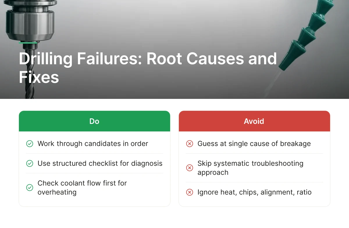
Most drilling failures trace back to four root causes, heat, chips, alignment, or feed-to-speed ratio, and isolating which one is the actual problem is the fastest path back to production. A structured checklist beats guesswork every time a batch starts producing scrap.
Diagnosing Tool Breakage, Hole Drift, and Poor Surface Finish
Tool breakage rarely has one cause, so work through the candidates in order of likelihood. Overheating shows up as discoloration on the flute or a burnt smell, usually pointing to insufficient coolant flow or a feed rate too slow for the spindle speed selected. Chip packing shows up as a sudden spike in torque mid-hole, common in deep or blind holes where chips have nowhere to evacuate. Misalignment produces a snapped tool right at entry, often from an undersized pilot hole or a center drill that skated off an uneven surface. A wrong feed-to-speed ratio produces steady, repeated failures across a run rather than a single random break, that pattern alone tells you the program, not the tool, is the problem.
Hole drift has three usual suspects. Entry geometry failure happens when there’s no starting cut to guide the drill, letting it wander before it engages fully. Tool runout, excess lateral movement in the spindle or holder, produces an oversized or oval hole even when the program is correct. Insufficient rigidity, whether from a long tool overhang or a thin-walled fixture, lets the whole system flex under cutting force. Check runout first with a dial indicator; it takes minutes and rules out half the possible causes.
Poor surface finish usually comes from one of four gaps: inadequate coolant reaching the cutting edge, a coating mismatched to the material, dull tooling past its wear life, or excessive feed leaving visible marks. Isolate the cause by swapping one variable at a time, fresh tool first, since dull edges are the most common and cheapest fix to rule out.
Process Refinements That Cut Cycle Time and Improve Hole Quality
Recording feed rate, speed, coolant pressure, and tool life after every job turns isolated fixes into a repeatable process refinement loop. Over several production runs, that record shows which parameter combinations hold tolerance consistently and which ones need adjustment before the next batch starts. This is where CNC hole drilling optimization stops being reactive troubleshooting and becomes a standing part of production planning.
At MFG SOLUTION, documented process parameters feed directly into the ISO 9001:2015 and IATF 16949 quality systems governing every batch, so lessons from one run carry forward instead of getting relearned on the next.
Frequently Asked Questions
What size range does CNC hole drilling optimization typically apply to for precision parts?
Most optimization work targets holes in parts up to roughly 38mm in diameter, where tolerance stacking and tool deflection matter most. Smaller parts amplify small errors in feed rate, runout, or coolant delivery, so shops running high-volume batches in this range see the biggest returns from tightening drilling parameters and tool selection.
Can you switch drilling methods mid-production if hole quality issues appear?
Yes, switching methods mid-run is possible but adds cost and requires requalifying the process before resuming full production. A shop with multiple capabilities on hand, CNC turning, Swiss lathe, or mill-turn, can pivot faster than one locked into a single machine type, since fixturing and programming for an alternate method are already in place.
Does optimizing for speed always reduce hole accuracy?
No, faster cycle times don’t automatically mean looser tolerances. Speed and accuracy compete only when feed rates push past what the tool, material, and machine rigidity can support. Below that threshold, better tooling, programming, and coolant delivery can cut cycle time while holding or improving hole quality.
How often should tooling be inspected to prevent drilling defects?
Inspect drill bits at set intervals tied to material and hole count, not on a fixed calendar schedule. High-volume runs in harder alloys need more frequent checks for wear and runout, since a dulling tool often causes defects before it visibly fails.
Conclusion
Reducing cycle time on precision holes comes down to three decisions: matching the drilling method to the part geometry, controlling chip evacuation and coolant delivery before scaling up feed rates, and inspecting tooling on a schedule tied to actual wear, not the calendar. Skipping any one of these tends to show up later as scrap or rework, which costs more than the time saved upfront.
If you’re sourcing parts under 38mm and need a partner that can match method to spec, submit a drawing to MFG SOLUTION for an 8-hour quote and see which of its five production methods fits your tolerance and volume requirements.
Recommended Articles
Explore more from our content library: