
2026-09-16
Tolerance and Depth in Part Design for CNC Hole Drilling
Understanding CNC hole drilling design is essential. Designing parts for CNC hole drilling means matching hole size, depth, and tolerance to what a drill bit and machine setup can reliably hold, before the part reaches the shop floor. Holes deeper than about 4-6x their diameter need peck cycles or specialized deep-hole drilling, which slow cycle time and raise cost. Tolerances tighter than standard drilling accuracy require secondary operations like reaming or boring. Getting hole placement, size, and depth-to-diameter ratio right in CAD avoids tool breakage, mislocated holes, and costly re-machining after parts are already cut.
Verify Your Hole Requirements Before Starting CNC Hole Drilling Design
Before a single hole goes into your CAD model, confirm its type, function, and callout, these three checks catch most CNC hole drilling design errors before they reach the shop floor.
A hole is not a generic cylinder. A through hole, a blind hole, a counterbore, and a threaded hole each place different demands on a drill bit, and each carries different risk of tool deflection or breakage. Through holes clear the far side and let chips evacuate freely; blind holes trap chips at the bottom, which raises heat and wear unless the program includes peck cycles. Counterbores require a step operation after the pilot hole, and threaded holes need a tap drill sized to the exact thread class, get that undersized or oversized, and the tap either binds or produces a loose, out-of-spec thread.
Can a CNC Machine Drill All Types of Holes?
No, not every hole shape or entry condition is drillable as designed, and some geometries need to be redesigned before they reach a machine.
A hole smaller than standard drill sizes may require a custom or undersized special tool, adding cost and lead time. An angled entry point on a curved or sloped surface causes the drill to skate sideways before it bites, a problem often called bit walk, and it can snap smaller-diameter bits outright. Intersecting holes, where one bore breaks into another, leave the drill without full material contact on one side, which deflects the tool and produces an oversized or oval result instead of a round one.
How Hole Placement and Size Mistakes Affect Assembly
Poor hole placement and incorrect size callouts are the two most common causes of cracked walls and failed assemblies in machined parts.
A hole placed too close to an edge, or too close to a neighboring hole, leaves a thin wall of material between them. That wall can flex under drilling pressure or crack outright, especially in aluminum and other softer alloys. On the size side, an oversized hole callout leaves excess play so a bolt rattles instead of seating; an undersized callout causes binding during assembly or forces a fastener that never fully seats. Before finalizing any drawing, define whether the hole is a clearance hole, a press-fit hole, or a tapped hole, that single decision determines which tolerance band and surface finish actually matter, and which ones you can relax to save cost.
Set Tolerance and Depth Limits for CNC Hole Drilling Design
Tolerance and depth-to-diameter ratio are the two variables that decide whether a hole comes off the drill as a finished feature or needs a second operation to correct it. Get either one wrong in a CNC hole drilling design and the part either costs more to make or fails to assemble.
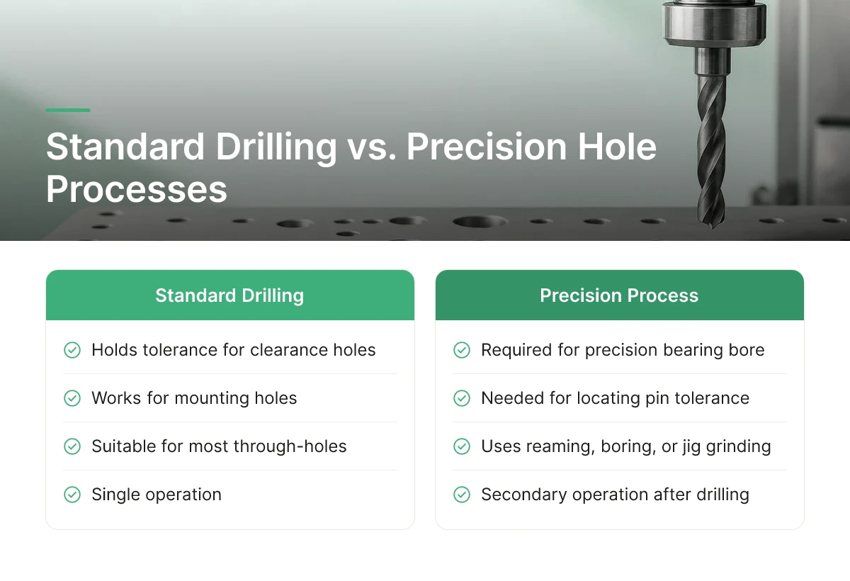
Standard drilling on a CNC lathe or mill holds a tolerance band that works for clearance holes, mounting holes, and most through-holes without any extra step. Push the requirement tighter, into the range needed for a precision bearing bore or a locating pin, and the process shifts to reaming, boring, or jig grinding after the drill clears the bulk material. Each of those secondary operations adds a setup, a tool change, and inspection time, all of which show up in the quote. A designer who specifies a tight tolerance on a hole that only needs to pass a fastener is paying for accuracy the part will never use.
What Is Hole Tolerance Stack-Up and How Does It Affect Fit?
Stack-up is what happens when several toleranced holes on one part each carry their own positional error, and those errors add up to determine whether the part mates correctly with its neighbor. A single hole at the edge of its tolerance band rarely causes a problem. Four or five holes on a bracket, each drifting toward the same side of their allowable range, can shift a bolt pattern enough that fasteners bind or a mating plate won’t seat flush. Designers should tolerance the hole pattern as a group, using a positional tolerance relative to a common datum, rather than tolerancing each hole independently, which tends to overstate the precision needed and understate the real risk of misalignment.
How Deep Can a CNC Machine Drill Before Needing a Different Approach?
Depth-to-diameter ratio measures how many diameters deep a hole goes; a 5mm hole drilled 25mm deep has a 5:1 ratio. Standard twist drilling handles ratios up to roughly 4-6x diameter in a single pass. Beyond that, chip evacuation becomes unreliable, heat builds up faster than the flutes can carry it away, and the drill itself starts to deflect, producing taper or an exit hole that lands off-center. Machinists manage this with peck drilling cycles that retract the tool to clear chips, or switch to gun drills built for deep, straight holes, both approaches that slow cycle time and raise cost per part. Blind holes make the problem worse since there’s no second opening for chips or coolant to escape.
The practical rule: loosen tolerance and shorten depth-to-diameter ratio everywhere the function allows, and reserve tight calls for the handful of holes that actually determine fit or performance. MFG SOLUTION’s engineering team reviews these calls during the 8-hour quoting window, flagging holes where a tolerance or depth adjustment avoids a secondary operation without compromising the part.
Configure Hole Drilling Parameters in Your CAD Model
Use dedicated hole-feature tools instead of generic cut extrusions, and flag every tolerance directly on the model so nothing gets lost between design and the CNC programmer’s screen.
This is where CNC hole drilling design either holds together or falls apart. A hole modeled as a simple cut carries no manufacturing intent, no callout for depth reference, thread class, or fit. A hole built with a dedicated hole feature carries that data natively, and it survives the export to STEP or drawing formats far more reliably.
How to Set Up Hole Parameters in Fusion 360, SolidWorks, or AutoCAD
- In Fusion 360, use the Hole command rather than Extrude-Cut. It lets you set diameter, depth type (blind, through-all, or to-object), drill point angle, and thread designation in one dialog, and that data stays attached to the feature tree.
- In SolidWolks, the Hole Wizard does the same job, pick a hole type (simple, tapped, counterbore, countersink), select a standard size from the fastener library, and specify termination depth explicitly rather than eyeballing it against a face.
- In AutoCAD, where 3D solid modeling is less common, define holes on 2D drawings using explicit diameter and depth dimensions plus standard ANSI or ISO hole symbols, since AutoCAD has no parametric hole feature to carry that intent forward automatically.
- Add tolerance and fit callouts, H7, H9, or a specific plus/minus range, directly on the dimension, not in a separate note that can get dropped during file conversion.
Consistency matters more than which tool you pick. A hole chart or feature tree that mixes generic cuts with proper hole features forces the programmer to double-check every dimension by hand, which adds review time before the quote can even be finalized.
Which CNC Drilling Cycle Should You Use for Each Hole Type?
Match the cycle to the hole’s depth-to-diameter ratio and finish requirement, and call that out on the drawing instead of leaving it to the machinist’s judgment.
- Standard drill cycle: appropriate for holes with depth under roughly three to four times the diameter, where chip evacuation isn’t a concern.
- Peck drilling: required for deeper holes, where the tool retracts periodically to clear chips and prevent heat buildup, specify this on any hole exceeding a 4:1 depth-to-diameter ratio.
- Boring or reaming: needed when a hole requires tight tolerance or a smooth bore finish beyond what a twist drill delivers, common on bearing bores or dowel pin holes.
Ambiguous callouts, a counterbore with no stated stack height, or a depth dimension with no stated reference face, force the shop to guess or stop and request clarification, which erodes any turnaround advantage. On parts with a dozen or more distinct hole sizes, add a hole chart keyed to letters or numbers on the drawing. MFG SOLUTION’s engineering team reviews incoming hole charts against machine capability for parts up to 38mm in diameter before quoting, which is part of how quotes return within 8 hours instead of after a round of back-and-forth emails.
Adjust Hole Design for Material, Cost, and Turnaround
Material hardness and hole geometry drive machining time directly, so CNC hole drilling design choices that ignore either one usually cost more or ship slower than necessary.
How Feed Rate and Bit Selection Change Across Titanium, Stainless Steel, and Composites
Titanium and stainless steel resist cutting far more than aluminum, which forces slower feed rates to avoid work hardening, chipped edges, or snapped bits. A shop running aluminum at a given feed rate typically has to cut that rate substantially for stainless and again for titanium, and each pass generates more heat, which means more frequent bit changes as coatings wear down. Coated carbide or cobalt bits replace standard high-speed steel for these materials, and the added tool changes stack up across a production run, every swap stops the spindle, resets the program, and adds non-cutting time that a customer eventually pays for.
Composites need a different approach entirely, not just a slower version of metal drilling. Layered fiber materials delaminate when a standard twist drill pushes through instead of shearing cleanly, leaving frayed edges or separated plies at the exit face. Specialized bit geometries, brad-point or compression-style tips, cut the surface fibers before the flutes engage the layer beneath, and backing material behind the exit face gives the fibers something to push against instead of tearing free. Designers who spec composite parts should flag this early, since a drilling plan built for aluminum will damage the part regardless of how carefully the feed rate is set.
Why Hole Count and Size Variation Drive Cost More Than Diameter Alone
Every unique hole diameter on a part usually means a separate tool change, and tool changes add fixed time regardless of how small the hole is. A part with six different hole sizes forces six tool swaps per cycle, multiplied across the batch, on a run of several thousand parts, that non-cutting time adds up faster than the actual drilling does. Standardizing on two or three common diameters instead of eight, where function allows, cuts tool changes without touching fit, clearance, or fastener compatibility.
This is where cost tiers separate more by tolerance and material than by hole count alone. A design with loose tolerances in aluminum sits at the budget-friendly end; tight tolerances in titanium or stainless, especially with many unique diameters, push toward premium pricing because of slower feeds, more tool changes, and tighter inspection requirements. MFG SOLUTION quotes against these variables directly, designers who consolidate hole sizes and match tolerance to actual function typically see that reflected in the 8-hour quote turnaround, since fewer tool changes and simpler setups are easier to price and schedule for the standard 3-day ship window.
Common Mistakes to Avoid in CNC Hole Drilling Design
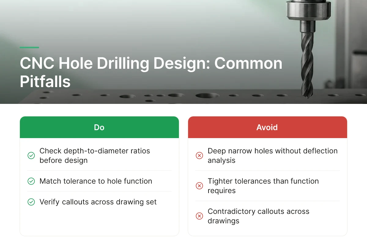
Most rework traces back to three repeat offenders: depth-to-diameter ratios that ignore drill deflection limits, tolerances tighter than the hole’s function requires, and callouts that contradict each other across a drawing set. Fixing these before the design leaves your desk is far cheaper than fixing them after a quote comes back flagged.
Unrealistic depth-to-diameter ratios show up when a designer specs a deep, narrow hole without checking whether a standard twist drill can hold straightness that far down. Beyond roughly 10:1, walking and deflection become hard to control without peck cycles, pilot holes, or specialty tooling, and if the drawing does not call that out, the shop has to stop and ask. Over-tight tolerances on non-critical holes are just as common: a clearance hole for a bolt does not need reamed-hole precision, but a drafter copies a tolerance block from a critical bore elsewhere on the part and applies it everywhere. Inconsistent callouts, one view showing a hole as a basic dimension, another showing it toleranced, a third silent on depth, force the machinist to guess, and guessing is where scrap comes from.
What Are the Cost and Speed Tradeoffs Between CNC Drilling, Laser Cutting, EDM, and Punching?
CNC drilling wins on flexibility for varied hole sizes in one setup; laser cutting, EDM, and punching win in specific situations where drilling’s mechanics work against you.
Laser cutting handles thin sheet stock efficiently because it does not need a physical bit engaging material, it is a strong fit for high volumes of small holes in gauge material where drill breakage or bushing wear would slow a drilling operation down. EDM earns its place on hardened tool steels and other materials too hard for conventional drills to cut without excessive wear; it removes material by electrical erosion rather than cutting force, so hardness stops being the limiting factor. Punching outperforms both when the geometry is non-round or repeats across a large batch on flat stock, a punch press stamps the shape in one stroke, and for high-volume repeat geometry that stroke beats the setup-and-cycle time of drilling each hole individually. CNC drilling still leads when a single part needs several different hole sizes, depths, or angles in one setup, since retooling a punch die for every variation erases its speed advantage.
When a hole sits near a machine or process limit, deep-and-narrow, oversized-and-thin-wall, or tight-tolerance-on-a-shape a tool cannot easily reach, confirm the function and tolerance with the manufacturer before the design is finalized. MFG SOLUTION reviews specifications during the 8-hour quoting window and will flag a hole callout that risks rework, before it reaches the shop floor.
Frequently Asked Questions
Can a CNC machine drill an angled or curved-surface hole accurately?
Yes, but the tool needs a flat starting point or a 5-axis setup to prevent drill wander. On curved or angled surfaces, a spotting drill or an end mill first cuts a small flat pocket so the drill bit doesn’t skate sideways on entry. Without that step, hole position can shift by several thousandths of an inch, especially on shallow angles.
What’s the difference between a blind hole and a through hole in terms of drilling difficulty?
Blind holes are harder to control because chips can’t clear as easily and depth must be held precisely at the bottom. Through holes let chips exit freely and tolerate small depth variation since the drill breaks through the far side.
How much does tightening a hole tolerance typically add to machining time?
Tightening a tolerance below roughly ±0.05 mm usually adds a secondary reaming or boring pass, extending cycle time and cost. Standard drilled tolerances (around ±0.1 mm) need no extra operation. Anything tighter also usually requires slower feed rates and in-process gauging, which adds setup and inspection time beyond the cut itself.
Do I need to specify chamfers on drilled holes?
Specify a chamfer whenever the hole will be tapped, deburred, or mated with another part. A 0.2–0.5 mm chamfer breaks sharp edges, guides fasteners during assembly, and reduces burr formation, particularly on softer metals like aluminum.
Is it better to drill or bore a hole that needs a tight tolerance?
Boring is generally the better choice once tolerance requirements go below what a standard drill can reliably hold. Drilling alone typically holds around ±0.1 mm, while boring can refine diameter, roundness, and surface finish well beyond that. The tradeoff is added cycle time and cost, so tight tolerances should be specified only where the part function actually requires them.
Conclusion
Reliable, cost-effective hole drilling comes down to three decisions: match hole depth to a diameter ratio your process can hold, specify tolerances only as tight as the function demands, and flag features like chamfers, blind-hole depths, and angled entry points before the design goes out for quotes. Each of these decisions affects cycle time and cost more than most designers expect.
Before submitting your next drawing, mark every hole that needs boring or reaming versus one that can run as drilled, that single callout change is often what separates an 8-hour quote from a design that bounces back for clarification.
Recommended Articles
Explore more from our content library: