
2026-10-04
How to Machine Tight Tolerances Without Slowing Production

Understanding how to machine tight tolerances is essential. You machine tight tolerances without slowing production by matching the setup to the spec rather than over-engineering every part: use rigid workholding, verify tool wear and thermal conditions before a run, and inspect at set intervals instead of part-by-part. The tolerance band drives your method choice (CNC turning, Swiss lathe, or multi-axis) and your inspection cadence, not the other way around. Parts that need 0.01-0.05mm precision don’t require slower cycles if the process is controlled upstream: fixturing, tool selection, and in-process checks matter more than cutting speed alone.

How to Machine Tight Tolerances Without Slowing Down Your Production Line
A tolerance is “tight” relative to the part, not an absolute number, 0.05mm is loose on a 2mm pin and demanding on a 35mm shaft, so the real question is whether it holds in one setup or forces rework.
Engineers often treat 0.01mm and 0.05mm tolerances as separate categories. For small parts under 38mm diameter, both sit in the same practical zone: achievable on the right equipment, but only if the process is built around them from the start. The dividing line isn’t the number on the drawing. It’s whether the part can be machined complete in a single setup, or whether it needs a second operation, a re-fixture, and a second inspection pass to get there. That second path is where production timelines actually break down, not the cutting itself.
This is the part of the puzzle most people get backward when they think about how to machine tight tolerances under deadline pressure. Tighter tolerance bands don’t require slower spindle speeds or longer cycle times by default. They require more rigorous setup: verified workholding, confirmed tool condition, stable thermal conditions in the shop, and inspection at the right intervals. Skip any of those, and the tolerance slips regardless of how slowly the machine runs. Get them right, and cycle time barely changes.
How Tolerance Requirements Affect Your Choice Between CNC, Manual, and Multi-Axis Machining
The tolerance spec should decide the machine, not the other way around. CNC turning handles moderate tight tolerances reliably across batch runs because it removes operator variability and holds repeatability across hundreds of parts. Swiss lathe machining earns its place on small, slender parts where rigidity is the limiting factor, guide bushing support lets the bar stock stay supported near the cutting point, which matters once tolerances tighten on long, thin geometries. Manual machining still has a role for one-off or low-volume work, but it depends on operator skill for repeatability and rarely scales to batch production without tolerance drift. Multi-axis mill-turn setups earn their cost when a part’s tolerance requirements span multiple features, holes, threads, contours, that would otherwise need separate operations; doing it in one setup removes the re-fixturing error that stacks up across operations.
At MFG SOLUTION, this setup-to-spec matching happens before a quote goes out: parts up to 38mm are routed to CNC turning, Swiss lathe, or mill-turn based on tolerance and geometry, with quotes returned within 8 hours.
Planning fixturing, material, and tool selection around the tolerance upfront is what avoids the rework and re-inspection cycles that actually slow a production line down.
Set Up Your Machine and Workflow for Consistent Tight-Tolerance Results
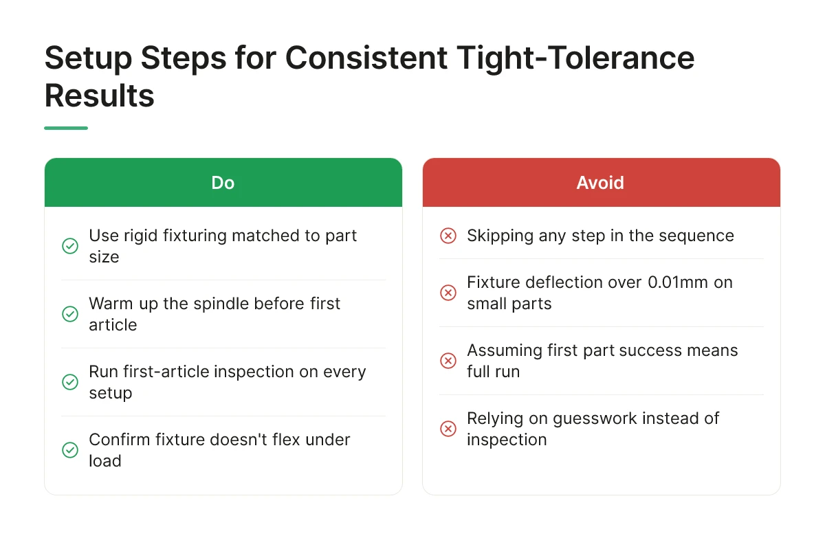
A repeatable setup sequence, rigid fixturing, matched tooling, a warmed-up spindle, and first-article inspection, is how to machine tight tolerances consistently across an entire production run, not just on the first part.
Skipping any one of these steps doesn’t always ruin the first part. It usually shows up as drift on part 40 or part 400, which is more expensive to catch late.
- Select and check the fixture. Confirm the workholding clamps the part without distorting it and that the fixture itself doesn’t flex under cutting load. For small parts under 38mm, even 0.01mm of fixture deflection can push a feature out of spec.
- Match tooling to the material. Tool geometry, coating, and insert grade need to suit the hardness and machinability of the stock, not a generic default.
- Warm up the spindle. Run the machine through its warm-up cycle before cutting production parts so thermal expansion in the spindle and ways stabilizes before you measure anything.
- Inspect the first article. Measure the first part against the full print, critical dimensions and non-critical ones, before releasing the machine to run unattended.
Workholding rigidity and setup count matter as much as the cutting parameters themselves. Each time a part gets unclamped and re-fixtured for a new operation, you introduce a new source of location error, and those errors stack. A single-setup process, where turning, milling, and drilling happen without moving the part, removes that stack-up entirely, which is why mill-turn and Swiss-style platforms hold tolerance more consistently on small, geometrically complex parts than a routing through three separate machines.
How Material Properties Affect Your Ability to Hold Tight Tolerances
Hardness, thermal expansion coefficient, and machinability determine the feed rate, cutting speed, and tool choice you need to hold a given tolerance, ignore them and the tolerance slips regardless of machine quality.
A free-machining brass and a hardened stainless alloy don’t behave the same way under a cutting edge, even at identical programmed feeds. Harder materials generate more cutting heat and tool wear, which changes dimensions mid-run if speeds aren’t adjusted. Materials with a high thermal expansion coefficient can grow measurably between the moment they’re cut and the moment they’re inspected at room temperature, which matters most on parts with tolerances in the thousandths of a millimeter. Machinability ratings also affect achievable surface finish, which ties directly into how tight a dimensional tolerance is realistically holdable on a given feature.
Consider two approaches to the same small part: a Swiss lathe cutting it complete in one setup, versus a multi-operation CNC mill routing that requires several re-fixturing steps. The Swiss lathe setup carries lower stack-up risk because the part never leaves its original reference position. The multi-operation route can still hold tight tolerances, but each re-clamp is a point where alignment error can creep in, which is why MFG SOLUTION matches each part to the process least likely to introduce that risk, choosing between Swiss lathe, CNC turning, or CNC mill & turn based on geometry rather than defaulting to one method for every job.
Verify Tolerances With the Right Inspection Tools and Schedule
Matching the measurement tool to the tolerance band, and checking parts on a schedule tied to wear rate, not guesswork, is how to machine tight tolerances without drowning in inspection time or shipping scrap.
Which Inspection Tools—CMM, Optical Comparators, or Others—Fit Which Tolerance Band
Not every feature needs the same instrument, and picking the wrong one wastes time or hides real deviation.
- Calipers and micrometers handle routine dimensional checks on straightforward features, outer diameters, lengths, simple bores, where tolerance bands sit in the range a skilled operator can confirm by hand in seconds.
- Coordinate measuring machines (CMMs) step in for complex geometry, true position callouts, and certified tolerance bands that require documented, repeatable data. Modern CMMs and high-resolution feedback systems can validate dimensional accuracy down to sub-micron levels, which matters when a print specifies ±0.0025 mm or tighter.
- Optical comparators and vision systems cover small or delicate features that calipers would damage or distort, thin walls, fine threads, miniature radii, by measuring without physical contact.
At MFG SOLUTION, parts up to 38mm in diameter move through this same logic: routine features get hand-tool checks, critical bands get CMM verification, and delicate geometries get optical measurement before anything ships.
How Often You Should Inspect Parts to Catch Tolerance Drift Early
Inspection frequency should track tool wear and run length, not a fixed interval applied blindly across every job.
Three checkpoints justify different levels of scrutiny. First-article inspection confirms the setup is correct before a batch runs, non-negotiable on any job with tight bands, since an error caught at part one costs far less than one caught at part 500. In-process sampling then checks parts at intervals through the run; how tight those intervals are should scale with how fast the cutting tool wears and how tight the print tolerance is. A long run on a tool with a known wear curve needs more frequent sampling as the tool approaches its service life, not a flat “check every 50th part” rule that ignores where the drift actually happens. Final inspection closes the loop, confirming the last parts off the machine still meet spec before packaging.
Inspecting every single part rarely makes sense for cost-effective production, it adds cycle time without adding much detection value if the process is stable. The goal is to catch drift before it produces scrap, not to achieve 100% inspection coverage.
Documentation ties the whole schedule together. Recording first-article results, in-process sample data, and final inspection numbers creates a traceable record, every step tracked and auditable, which matters for regulated industries like medical devices and automotive, where process control isn’t optional. This is the kind of full process control that ISO 9001:2015, ISO 13485:2016, and IATF 16949 certifications are built to verify, without requiring any claim beyond what those standards already cover.
Diagnose and Fix Tolerance Failures Before They Stall Production
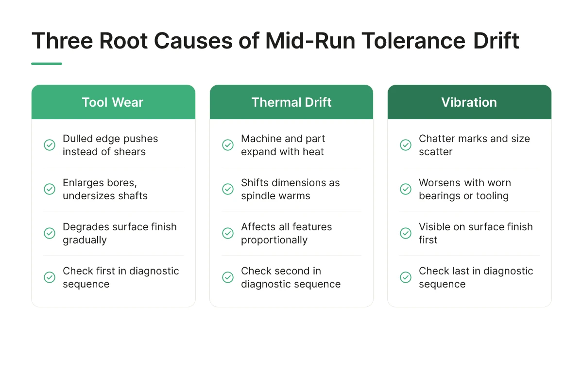
Most mid-run tolerance failures trace back to one of three causes: tool wear, thermal drift, or vibration, and checking them in the wrong order wastes hours chasing a variable that was never the problem. Knowing how to machine tight tolerances consistently means knowing how to diagnose a drift fast, not just how to cut the part correctly the first time.
How Tool Wear, Thermal Drift, and Vibration Affect Tolerance Hold
Tool wear changes cutting geometry gradually. As a cutting edge dulls, it pushes harder into the material instead of shearing it cleanly, which enlarges bores, undersizes shafts, and degrades surface finish, often in a slow drift that looks like a process problem before anyone suspects the insert.
Thermal expansion works faster and less predictably. Spindles, workpieces, and even coolant lines expand as a machine heats up during the first 20-40 minutes of a shift, shifting dimensions before the system reaches thermal equilibrium. A part cut cold and a part cut after an hour of continuous running can land at opposite ends of the same tolerance band.
Vibration and chatter show up as the most visible symptom, poor surface finish, chatter marks, or inconsistent readings between parts that should be identical. It usually signals inadequate rigidity: a loose fixture, excessive tool stickout, or a workholding setup that can’t resist cutting forces at the required feed rate.
Work the Diagnostic Order, Don’t Guess
Check causes in a fixed sequence to avoid wasting a shift on the wrong fix:
- Measurement and gauge calibration first. A drifting micrometer or an out-of-cal CMM will make a good part look bad and send you hunting for a machine problem that doesn’t exist.
- Tool condition second. Pull the insert or tool and inspect wear under magnification, or check the part trend, gradual drift over dozens of parts points here.
- Thermal state third. Compare morning-run dimensions against mid-shift dimensions. A consistent offset that stabilizes after warm-up confirms thermal expansion, not tooling.
- Fixture rigidity last. If dimensions are erratic rather than trending in one direction, and surface finish is poor, suspect vibration from workholding or tool deflection.
Fix the Root Cause, Not the Symptom
Replace tools on a scheduled interval based on wear curves for the specific material and cutting parameters, rather than waiting for a part to fail inspection. Run a warm-up cycle before any tight-tolerance job so the machine reaches thermal equilibrium before parts that matter get cut. Address vibration with added damping, shorter tool stickout, or re-fixturing rather than slowing feed rates, which hurts throughput without solving the underlying rigidity issue.
When parts start falling out of spec mid-run, stop the line immediately. Isolate one variable at a time using the order above, make the correction, then run and inspect a first-article part before resuming full production, resuming without that check risks scrapping an entire batch on the same undiagnosed cause. MFG SOLUTION builds this discipline into its process control under ISO 9001:2015 and IATF 16949, where every corrective action is documented and traceable back to the specific cause.
Common Mistakes to Avoid When Machining Tight Tolerances Under Deadline
Most deadline blowouts come from treating every dimension as equally critical instead of ranking features by what actually affects fit and function.
The pressure looks different across industries, but the tradeoff is the same: speed versus precision, with no free lunch. Medical device makers need ±0.0025 mm accuracy on critical features like luer fittings or implant interfaces, but quality systems and full documentation slow down every batch. Automotive suppliers run high volumes where a single out-of-spec connector pin can stop an assembly line, so they lean on CNC repeatability over manual processes to hold tolerance at speed. Electronics manufacturers machining small connector housings and contacts under 38mm face tight fit tolerances on mating surfaces, but tolerance that’s too tight everywhere just adds cost without improving the connection. Each industry has a different threshold for what “tight” means, but all three lose time when tolerance decisions get made reactively instead of upfront.
Mistake 1: Over-Specifying Tolerance on Non-Critical Features
Calling out ±0.0005″ across an entire print instead of only on mating surfaces can double machining time and increase inspection costs by roughly 40%. That cost doesn’t buy better function, it buys slower cycle times, more scrapped parts, and inspection reports nobody reads. A bracket’s mounting hole might need to hold a tight tolerance, while its outer profile can run standard tolerance with no impact on assembly.
Mistake 2: Inspecting Everything the Same Way
Shops that treat every dimension as equally urgent to measure spend inspection time on features that never cause rejects, while critical dimensions get the same cursory check as everything else. Inspection effort should scale with risk: weight CMM time and sampling frequency toward the two or three dimensions that drive fit, sealing, or electrical contact, and spot-check the rest.
Getting the Upfront Decision Right
Learning how to machine tight tolerances without blowing deadlines comes down to one decision made before the first cut: which dimensions are critical, and which can run standard tolerance. MFG SOLUTION’s engineering team reviews specs during the 8-hour quoting window specifically to flag over-tolerancing before it adds cost, then manufactures under ISO 9001:2015, ISO 13485:2016, and IATF 16949 process control so the critical features get the inspection rigor they need, without taxing every dimension on the print.

Frequently Asked Questions
Is 0.01 mm or 0.05 mm considered a tight tolerance for small parts?
Both count as tight by general machining standards, but 0.01 mm sits closer to the precision ceiling for conventional CNC turning and milling. A tolerance of ±0.0025 mm or better is considered ultra-precise and usually demands specialized equipment with thermal compensation. For most small parts under 38 mm, 0.01-0.05 mm is achievable with disciplined process control rather than exotic tooling.
What troubleshooting steps should you follow when parts start falling out of spec?
Stop the run, pull the last in-spec part for comparison, and check tool wear first, it’s the most common cause of tolerance drift. Next, verify workholding hasn’t shifted and confirm the machine hasn’t drifted thermally during a long cycle. Re-measure your fixture offsets before restarting, and log the deviation so the pattern doesn’t repeat on the next batch.
How do you balance the cost of tight tolerances against the speed your customer needs?
Apply tight tolerances only to the surfaces that actually require them, and hold standard tolerances everywhere else. Over-specifying a full part to ±0.0005″ can double machining time and raise inspection costs by roughly 40%. MFG SOLUTION addresses this by matching each feature to the most economical of five processes, CNC turning, Swiss lathe, cold forging, automatic lathe, or mill-turn, so speed and cost don’t trade off against precision.
Do tight-tolerance parts always require a CMM for inspection?
No, CMMs are necessary for complex geometries or sub-micron validation, but simpler critical dimensions can be checked with calibrated micrometers or optical comparators. Coordinate measuring machines remain the standard for validating dimensional accuracy at sub-micron levels on medical or aerospace parts.
Conclusion
Holding tight tolerances without blowing your budget or your deadline comes down to three disciplines: specify tight tolerances only where function demands them, control the variables that cause drift, tool wear, workholding, thermal shift, and inspect with the right tool for the job, not the most expensive one. Parts over-specified across every surface routinely cost 30-50% more than they need to, while the function-critical dimensions are often a small fraction of the print.
Next step: pull your current part drawing, flag which dimensions are truly critical to fit or function, and get a quote against that revised spec, MFG SOLUTION returns quotes within 8 hours, so you can compare cost impact before committing to a production run.
Recommended Articles
Explore more from our content library: