
2026-09-30
6 Ways to Improve CNC Machining Surface Finish on Metal
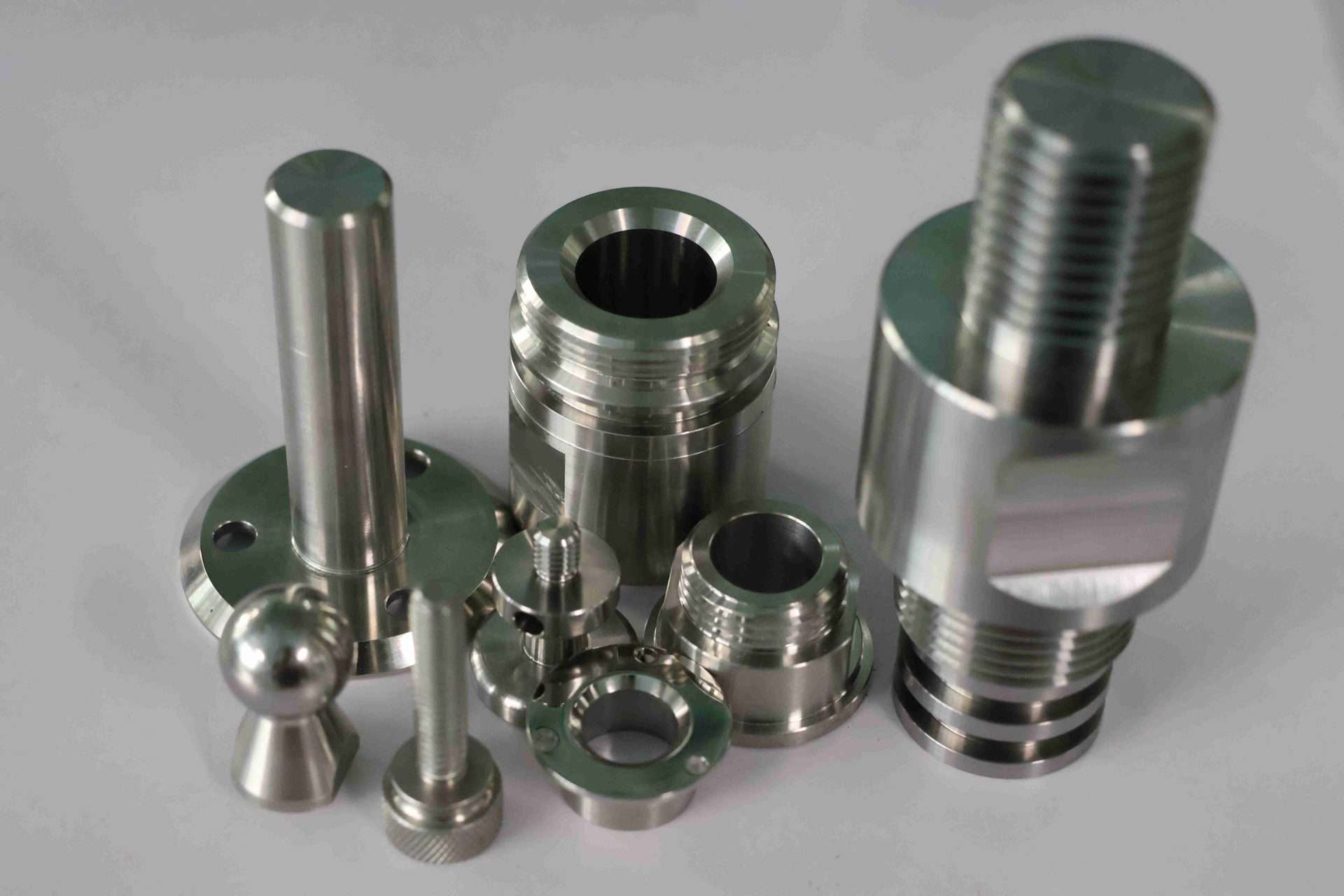
Tighter CNC machining surface finish comes from controlling the variables that create roughness before parts ever leave the machine: tool selection, cutting speed and feed, coolant strategy, material behavior, and machine rigidity. Getting these right in-process reduces or eliminates secondary finishing steps like bead blasting or polishing, which cuts both cost and lead time. The six approaches below—covering tooling, parameters, defect prevention, material choice, finishing methods, and correct specification—give you a practical path to meeting customer surface finish callouts without over-processing or overspending. For a broader primer on the metrics involved, this practical guide to CNC surface finish is a useful companion reference.

1. Optimize Tool Selection and Cutting Speed to Control CNC Machining Surface Finish
Tool geometry and cutting parameters set the ceiling on achievable roughness before any secondary process gets involved, making this the single highest-use decision in the process.
Which Cutting Tool Geometries and Coatings Produce the Finest Surface Finishes
A larger nose radius leaves a shallower scallop between passes, directly lowering the peak-to-valley height that defines Ra . Sharper cutting edges shear material instead of tearing it, which matters most in softer or gummy alloys prone to smearing.
Coatings change how the edge behaves over time, not just on the first cut. TiAlN coatings resist heat buildup during dry or high-speed cuts, while diamond-like carbon coatings reduce friction on aluminum and nonferrous parts, delaying the edge degradation that eventually shows up as roughness on the part surface. Choosing the right tool and coating combination is one of the fastest ways to improve CNC machining surface finish without adding a secondary operation.
How Tool Wear Progression Impacts Surface Finish Consistency
A fresh tool and a tool 200 parts into a run cut differently, even at identical parameters. As flank wear increases, the effective cutting geometry changes, and Ra values creep upward part by part rather than failing all at once.
A dedicated finishing pass at a lower feed per tooth, run separately from the roughing pass, recovers the surface quality that roughing sacrifices for material removal rate. Shops running long batches gain more from wear monitoring and scheduled tool changes than from any single “perfect” setup, because the real challenge is holding CNC machining surface finish steady across hundreds of parts, not producing one good sample.
2. Tune Feed Rate, Spindle Speed, and Coolant Strategy
Feed rate, spindle speed, and coolant delivery work together to reduce cusp height and clear heat and chips before they mar the surface.
What Feed Rates and Spindle Speeds Work Best for Small-Diameter Parts
Theoretical surface roughness scales with feed per revolution and inversely with nose radius, cut the feed in half and the cusp height drops sharply, which is why finish passes always run slower than roughing passes . For parts up to 38mm in diameter, this relationship gets more sensitive as length-to-diameter ratio increases, since slender turned parts flex and vibrate at spindle speeds that would run clean on shorter, stockier geometries.
That chatter risk caps how aggressively spindle speed can be pushed on small-diameter work, regardless of what the tool and coating can theoretically handle. For a deeper look at how these parameters interact with roughness values, see this surface roughness guide covering Ra and Rz.
How Coolant Type and Application Method Influence Finish Quality
Coolant does two jobs at once: it pulls heat out of the cutting zone and flushes chips before they get re-cut into the surface. Coolant strategies generally fall into a few categories, each suited to a different stage of the job:
- Flood coolant — works well for general turning and roughing operations where volume matters more than precision targeting.
- Mist coolant — suits lighter finishing operations where excess fluid could interfere with the cut.
- Through-tool coolant delivery — becomes necessary on deep or small-bore features where chips would otherwise pack against the tool.
Poor chip evacuation causes built-up edge and re-cutting, both of which show up as inconsistent texture rather than a uniform finish. Slower feeds and richer coolant strategies improve finish, but they also add cycle time, a deliberate trade-off against cost, not a setting to default to on every job.
3. Prevent Chatter, Tool Marks, and Other Common Surface Defects
Most surface defects trace back to three causes, resonance, built-up edge, and heat, each with a distinct fix that doesn’t require blaming the material first.
What Causes Chatter, Micro-Cracks, and Built-Up Edge
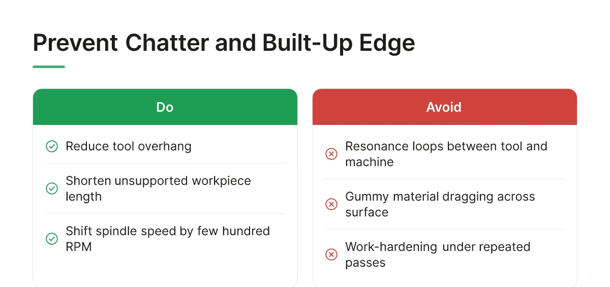
Chatter is a resonance loop between tool, workpiece, and machine structure, once it starts, it feeds on itself and leaves a rippled pattern the eye can see and a caliper can’t fully explain. Reducing tool overhang, shortening the workpiece’s unsupported length, or shifting spindle speed a few hundred RPM breaks the resonance cycle without changing the program.
Built-up edge forms when gummy or work-hardening materials weld small fragments onto the cutting edge at certain speed ranges, then tear off unevenly, leaving a rough, inconsistent surface. Adjusting speed and improving coolant contact at the cutting zone usually eliminates it. Micro-cracks are a separate risk, appearing when excessive heat or an overly aggressive finishing pass thermally shocks hardened materials, compromising the surface even when the dimensions still check out.
How to Troubleshoot Surface Finish Problems Mid-Production
Work the cheapest explanation first. Check tool wear, because a dulling edge is the most common and fastest-changing variable in any run. Next, review feed, speed, and coolant settings against the job’s baseline parameters.
Only after ruling out tooling and parameters should rigidity, fixturing, overhang, or machine condition, get investigated, and material variation should be the last suspect, not the first assumption. Holding tight dimensional control alongside a consistent CNC machining surface finish often depends on the same fixturing and rigidity checks described in this guide to achieving tight tolerances in manufacturing.
4. Choose Materials That Machine to a Better Natural Finish
Material choice sets a practical floor on achievable roughness, since some alloys cut cleanly while others tear, smear, or work-harden under the same tool path.
Do Aluminum, Stainless Steel, and Other Materials Machine to Different Natural Finishes
Free-machining grades, leaded brass, resulfurized stainless, form short, clean chips that break away without dragging across the finished surface. Gummy or work-hardening alloys do the opposite: they smear, drag, and harden further wherever the tool has already passed, making each subsequent pass harder than the last.
Aluminum typically finishes smoother at higher cutting speeds than stainless steel, which work-hardens quickly and demands lower speeds, sharper tools, and more attentive coolant strategy to avoid the same surface degradation. Material choice also matters when comparing machining against other production methods; this comparison of CNC machining versus casting outlines why machined parts generally hold a finer as-produced surface than cast ones.
Can Certain Materials Reach Acceptable Finish Without Post-Processing
A part machined from a free-machining aluminum or brass grade, with the right tooling and finishing pass, can often be left as-machined for non-critical cosmetic or functional surfaces. Hardened tool steels, coarse-grain castings, or parts with tight sealing or medical-contact requirements usually can’t skip secondary finishing, because grain structure or hardness limits how fine the as-cut surface can get.
This decision connects directly to material selection choices made earlier in the design process, grades like 15-5 and 17-4 PH stainless behave differently under the same cutting conditions and warrant their own evaluation before assuming a finish target is achievable as-machined.
5. Apply the Right Secondary Finishing Method for Small Precision Parts
Bead blasting, electropolishing, and anodizing each fix a different limitation left by in-process control, and picking the wrong one risks the tolerances the machining already achieved.
What Is the Cost and Lead-Time Trade-Off Between Finishing Processes
Bead blasting creates a uniform matte texture with minimal dimensional change, making it a budget-friendly, fast option when a part needs a consistent cosmetic finish rather than a functional one. Electropolishing works electrochemically, removing high points from the surface to leave it smoother and more corrosion-resistant, a common requirement for medical or food-grade parts that also need to be easy to clean . This overview of advanced surface treatment techniques covers how these processes are typically selected and combined.
Anodizing applies to aluminum parts needing wear resistance or color: Type II anodizing produces a thinner, more decorative layer, while Type III (hard anodizing) builds a thicker, harder layer at the cost of longer processing time. Electropolishing and hard anodizing generally sit in a mid-range to premium cost tier with longer lead times than blasting, reflecting the added process control involved.
Which Finishing Methods Preserve Tight Dimensional Tolerances
Bead blasting and thin Type II anodizing add negligible dimensional change and rarely threaten tight tolerances on small parts. Electropolishing and hard anodizing remove or add measurable material thickness, which can round sharp edges or shift critical dimensions on parts machined up to 38mm in diameter if the process isn’t accounted for in the original tolerance stack.
MFG SOLUTION addresses this by keeping finishing decisions tied to the same process control used in machining, parts are produced to ISO 9001:2015, ISO 13485:2016, and IATF 16949 standards, so any secondary finish applied downstream doesn’t undo the tolerance work already built into CNC machining surface finish on the shop floor.
6. Specify Ra, Rz, or Rt Correctly on Technical Drawings
Choosing the wrong roughness parameter on a drawing creates ambiguity that leads to rejected parts or unnecessary rework, even when the machine shop hits the numeric target.
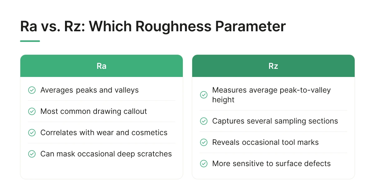
Ra (average roughness) averages the peaks and valleys over a sampling length, while Rz measures the average peak-to-valley height of several sampling sections, and Rt captures the single largest peak-to-valley distance across the entire trace. Ra is the most common callout on drawings because most profilometers report it by default and it correlates reasonably well with general wear and cosmetic behavior. But Ra can mask an occasional deep scratch or tool mark that Rz or Rt would catch, which matters for sealing surfaces or fatigue-critical parts where one deep valley can start a crack.
What Do Specific Ra Values Mean for Part Function and Customer Acceptance
A fine bearing or sealing surface typically calls for a low Ra value achieved through grinding, honing, or polishing, while a general cosmetic or non-mating surface can accept a coarser as-machined Ra straight off the tool. Matching the value to the actual contact condition—rather than defaulting to the tightest number available—keeps cost and lead time proportional to function.
How to Choose Between Ra and Rz When Customers Don’t Specify
When a print omits a parameter, default to Ra for general-purpose surfaces and flag Rz or Rt for any surface with a sealing, fatigue, or high-cycle-loading function. Surface finish symbols following ASME Y14.36 or ISO 1302 conventions should indicate the parameter, value, and sometimes the machining direction (lay); a bare triangle or checkmark without a stated parameter is the most common source of ambiguity on incoming drawings. CNC machining surface finish callouts that omit units or sampling length force the shop to guess, which is where scope disputes start.
If a callout looks tighter than the application needs, show the customer the added cycle time or secondary-finishing cost before committing, since a 0.4 µm Ra requirement on a non-mating face can double machining time for no functional gain. Validate the finished part with a stylus profilometer or a handheld roughness gauge referenced to the same parameter and cutoff length specified on the print.
How to Choose the Right Surface Finish Approach for Your Parts
Base the decision on three inputs: what the surface must functionally do, what the material can achieve as-machined, and how many parts you’re running.
A single prototype rarely justifies investing in slower feeds, specialized tooling, or a secondary finishing step—accepting a slightly rougher as-machined surface and moving on is usually cheaper. At production volume, though, the math flips: a small increase in per-part cycle time to hit a finish target in-process gets multiplied across thousands of units, and it often costs less than routing every part through an outside grinding or polishing vendor. Part criticality shifts that threshold further—a medical implant or a sealing bore justifies tighter in-process control at lower volumes than a cosmetic bracket would.
A short checklist keeps the decision grounded rather than driven by habit:
- Confirm the functional need behind the spec—sealing, fatigue resistance, bearing contact, or appearance—before accepting a tight number at face value.
- Match the material to its realistic as-machined finish; some alloys burnish well under a single-point tool, others tear and need a secondary pass regardless of feed rate.
- Select a finishing method only when the function actually demands it, not because a tighter number seems safer on paper.
Surface finish drives real outcomes: a rough sealing face leaks, a rough bearing surface wears prematurely, and a sharp machining mark at a fillet or shoulder becomes a stress concentration point that can start a fatigue crack. MFG SOLUTION applies this same function-first logic across CNC turning, Swiss lathe, cold forging, automatic lathe, and CNC mill and turn processes—selecting the method suited to the part’s diameter and criticality up to 38mm, then confirming the result against your drawing before the batch ships within 3 days of approval.

Frequently Asked Questions
Do finer surface finishes actually improve corrosion resistance?
Yes, but only up to a point, a smoother surface reduces the microscopic peaks and valleys where moisture and contaminants collect, which lowers pitting risk. Below roughly 0.4 µm Ra, further polishing usually adds cost without meaningfully improving corrosion performance; a suitable coating or material choice typically matters more than chasing an ultra-fine Ra value.
How does surface roughness affect fit and function on bearing or sealing surfaces?
Rougher surfaces increase friction, wear, and leak risk on bearing and sealing faces. On dynamic surfaces like shafts or O-ring bores, peaks can score mating parts or break a seal, while excess roughness on static seals creates leak paths, matching the finish to the mating component’s requirement matters more than defaulting to the tightest spec available.
What surface finish tolerances are typical across industries like automotive, medical, and electronics?
Requirements vary by industry and function, not by a single universal number. Automotive components like engine or transmission parts often need tighter finishes on critical bores; medical implants and surgical instruments frequently call for very smooth, biocompatible surfaces; electronics housings and connectors are usually less demanding unless they involve sealing or EMI shielding contact.
How do we qualify that finished parts actually meet a customer’s surface finish callout?
Qualification means measuring actual roughness against the drawing callout using a profilometer or comparator and documenting the result. MFG SOLUTION ships parts made to ISO 9001:2015, ISO 13485:2016, and IATF 16949 standards, meaning every finishing step is tracked and auditable so customers get traceable proof of CNC machining surface finish quality, not just a visual check.
What GD&T callouts do we need to understand when a customer specifies surface finish?
Surface finish typically appears as a roughness symbol (Ra or Rz value) attached to a specific surface or feature control frame, separate from dimensional tolerances. It’s read alongside flatness, cylindricity, or perpendicularity callouts, since a tight geometric tolerance often implies a finer finish is needed to hold that shape under inspection.

Conclusion
Surface finish decisions come down to three things: matching roughness to actual function instead of defaulting to the tightest number available, understanding the cost curve where finishes below 0.4 µm Ra add machining time without proportional benefit, and building measurement into the process rather than treating it as a final inspection step. Getting this wrong means paying for polish nobody needs or shipping parts that fail on a bearing surface.
If you’re specifying a finish for an upcoming part, submit your drawing to MFG SOLUTION for an 8-hour quote, the engineering team will flag whether your callout matches the part’s actual function before you commit to a production run.
Recommended Articles
Explore more from our content library: