
2026-11-07
CNC Machining for Industrial Woodworking Machinery: Spindle Housings, Roller Shafts, Guide Supports and Precision Machine Components

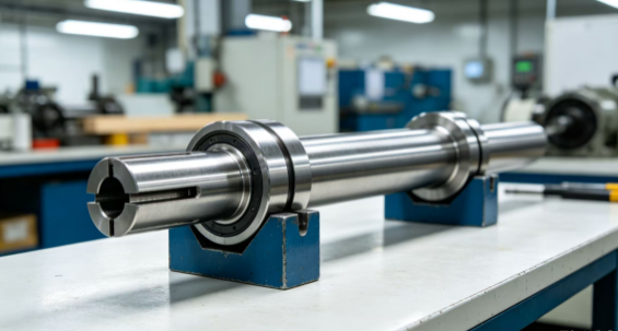
Industrial woodworking and furniture manufacturing equipment must maintain consistent mechanical performance under continuous production conditions. From panel processing centers and CNC routers to edge banding machines, drilling systems, sanding equipment and automated cutting lines, every machine depends on accurately manufactured mechanical components.
These machines process wood panels, solid timber, engineered boards and composite materials. Their operating environments can involve vibration, dust, repeated loading, high spindle speeds and frequent tool changes. Components must therefore provide reliable positioning, stable support and consistent mechanical connections.
Typical precision parts include spindle housings, roller shafts, bearing supports, cutter mounting blocks, guide rail brackets, clamping components, drive adapters and machine frame interfaces. Although these parts may not be as visible as the machine’s motors or control systems, their dimensions and mechanical relationships can directly affect equipment assembly and operating consistency.
CNC machining provides a flexible way to manufacture custom components for woodworking machinery. CNC milling, turning, drilling, boring and multi-axis machining can produce the required geometries from aluminum, steel, stainless steel, brass and selected engineering plastics.
For equipment manufacturers, successful component sourcing requires more than selecting a machining process. The design must account for tool access, bearing alignment, shaft geometry, mounting accuracy, material behavior, surface finish and inspection requirements.
MFG SOLUTION supports custom precision manufacturing for industrial equipment applications. This article explains the important considerations when producing CNC-machined components for woodworking machinery, from material selection and machining strategy to quality control, cost management and RFQ preparation.
1. Understanding the Mechanical Requirements of Woodworking Machinery
Industrial woodworking machines combine rotating tools, linear motion systems, material-feeding mechanisms, clamping assemblies and structural frames. Each subsystem depends on components that must maintain their intended position during operation.
A CNC router, for example, requires stable spindle mounting and accurate positioning between the spindle, tool and workpiece. An edge banding machine uses rollers, guides and clamping mechanisms to control panel movement. A sanding machine depends on roller alignment and consistent mechanical support.
Common component requirements include:
- Accurate bearing seats and shaft interfaces
- Stable mounting surfaces for motors and spindle assemblies
- Consistent positioning of guide rails and linear supports
- Reliable connections between drive components
- Appropriate stiffness under repeated mechanical loads
- Resistance to wear at moving or contacting interfaces
- Dimensional consistency across production batches
- Practical maintenance and replacement compatibility
A component that meets its individual dimensions may still cause assembly difficulties if its relationship with other parts is not controlled.
For this reason, equipment manufacturers should identify the important assembly datums and functional dimensions before finalizing machining requirements.
2. Common CNC-Machined Components in Woodworking Equipment
Different woodworking machines require different precision components. Understanding their functions helps determine suitable materials, machining processes and inspection methods.
Spindle housings and motor mounting blocks
Spindle housings support rotating assemblies and establish the mounting relationship between the spindle, bearings and machine structure.
Depending on the design, these components may contain precision bores, mounting faces, threaded holes, cooling passages and locating features.
The bearing bore and mounting geometry are particularly important. Their dimensional relationships can influence assembly alignment and the stability of the rotating unit.
CNC milling and boring are commonly used to produce these features. More complex housings may benefit from multi-axis machining when important surfaces are distributed across several faces.
Roller shafts and feed rollers
Panel-feeding and material-handling systems use rollers and shafts to guide boards through different machining stages.
These components may require stepped diameters, bearing journals, keyways, grooves, threads and coupling interfaces.
CNC turning is suitable for producing cylindrical features and maintaining the required relationship between shaft diameters. Secondary milling operations may be used for flats, keyways and other non-rotational details.
Guide rail supports and positioning brackets
Guide rail supports help maintain the position of linear motion components. They may be manufactured as blocks, plates, brackets or custom mounting structures.
Their important features can include mounting holes, locating faces, counterbores and machined reference surfaces.
If several supports are used along the same machine axis, their relative position and mounting geometry should be considered as part of the complete assembly.
Cutter holders and tool mounting components
Cutter holders, tool adapters and mounting blocks connect cutting tools to machine assemblies.
Their design may include precision bores, clamping slots, threaded holes, locating diameters and contact faces.
The machining plan should consider the required tool interface, material properties and dimensional requirements. Any critical clamping or locating surface should be clearly identified in the drawing.
Clamping blocks and workholding components
Woodworking equipment frequently uses mechanical or pneumatic clamping systems to position panels and workpieces.
Custom clamping blocks, support pads, stops and fixture components may require accurately machined contact surfaces and mounting features.
For these parts, the geometry should reflect the actual workpiece and clamping arrangement. The CNC workholding fixtures guide provides further information about fixture design and manufacturing considerations.
3. Material Selection for Woodworking Machine Components
Material selection affects strength, stiffness, wear resistance, machinability, weight and production cost.
The correct material depends on the component’s mechanical function and operating environment. A spindle support does not necessarily require the same material as a lightweight cover bracket or a sliding guide component.
Aluminum alloys
Aluminum alloys are commonly considered for mounting blocks, machine brackets, covers, adapters and selected structural components.
Their relatively low density and good machinability can help reduce component weight and machining time.
However, thin-wall aluminum parts may be sensitive to clamping pressure and material removal. The machining sequence should be designed to reduce deformation and maintain critical mounting dimensions.
For more information, see the MFG SOLUTION aluminum machining resource.
Carbon steel and alloy steel
Carbon and alloy steels may be suitable for shafts, bearing supports, structural interfaces, clamping components and parts exposed to repeated mechanical loading.
Different grades offer different combinations of strength, toughness, hardness and machinability.
Where a component requires heat treatment, the process should account for possible dimensional changes. Additional finishing operations may be needed after treatment to achieve the specified dimensions.
The 1045 steel turned parts guide provides a reference for steel turning applications.
Stainless steel
Stainless steel may be used for selected machine components exposed to moisture, cleaning agents or environments where corrosion resistance is important.
It can also be considered for particular fasteners, shafts, adapters and machine interfaces.
Grade selection should reflect mechanical loading, corrosion exposure and machining requirements. Stainless steel should not be selected automatically when a less expensive material can satisfy the actual application.
Review the stainless steel block machining guide for further information.
Brass and copper alloys
Brass and copper alloys may be appropriate for selected bushings, fittings, electrical interfaces and other components requiring specific material characteristics.
Their suitability depends on wear conditions, contact requirements, mechanical loading and the intended assembly.
Engineering plastics
POM, nylon, PEEK and other engineering plastics may be used for selected guide elements, spacers, sliding components, protective parts and non-primary structural interfaces.
Material selection should consider wear, friction, stiffness, temperature, moisture absorption and dimensional stability.
The MFG SOLUTION material selection resource can help engineering teams review material options before releasing a drawing for production.
4. CNC Turning for Roller Shafts, Spindles and Rotational Components
Rotational components are essential in woodworking equipment. They support material feeding, power transmission, tool positioning and mechanical movement.
CNC turning is suitable for producing shafts, rollers, sleeves, collars, spacers, bushings and other cylindrical parts.
Bearing journals and stepped diameters
A roller shaft may contain several diameters that perform different functions. Bearing journals locate the bearings, shoulders establish axial positions, and coupling diameters connect the shaft to a drive system.
These features should be machined with an appropriate datum strategy so that their dimensional relationships remain consistent.
Where concentricity or runout is important, the manufacturing plan should identify how these characteristics will be controlled and inspected.
Keyways and drive interfaces
Some shafts transfer torque through keyways, flats, splines or other mechanical interfaces.
These features are often produced through secondary milling operations. Their position relative to the shaft axis should be defined clearly.
The design should also provide enough information about the mating component to verify the intended fit.
Threads and retaining grooves
Shafts may include threaded ends, retaining grooves and other assembly features.
Thread specifications should identify the required diameter, pitch, thread class and engagement length. Grooves should have clearly defined dimensions where they affect retaining rings or other components.
See the precision thread tolerance guide for additional information.
Surface finish on rotating components
Bearing journals, sliding surfaces and general shaft diameters may have different finish requirements.
A fine finish should be specified where the functional design requires it. Applying the same high-finish requirement to every surface can add unnecessary manufacturing cost.
For more guidance, review the CNC machining surface finish guide.
5. CNC Milling for Spindle Housings and Machine Mounting Blocks
CNC milling is widely used for machine components with flat surfaces, pockets, slots, holes, mounting features and irregular profiles.
Spindle housings, motor adapters, guide rail blocks and custom brackets often combine several of these features.
Establishing reference surfaces
The first step is to understand how the finished component will be positioned in the machine assembly.
A machined bottom face may serve as the primary datum, while a side face or locating bore establishes orientation.
Critical holes and mounting features can then be controlled relative to these references.
This is particularly important when a component connects two separate machine assemblies.
Machining pockets and mounting holes
Machine components may contain recessed areas, counterbores, threaded holes and slots for adjustment.
Their design should consider cutter access, corner radii, hole depth and remaining wall thickness.
Extremely narrow pockets or deep cavities can increase machining difficulty and may require special tooling or additional operations.
Choosing three-axis or five-axis machining
Three-axis CNC machining can handle many conventional mounting blocks and support components.
Four-axis or five-axis machining may be useful when the part contains angled holes, features on several faces or complex geometry that is difficult to access through conventional setups.
The choice should reflect component geometry, tolerance relationships, production volume and overall manufacturing cost.
Explore five-axis CNC machining and the general CNC machining service for additional information.
Managing thin walls and machining deformation
Some brackets and housings contain thin walls or uneven material distribution.
Excessive clamping force can deform the workpiece. Aggressive material removal may also release internal stresses and affect dimensional stability.
A suitable workholding strategy and staged machining sequence can help reduce these risks.
6. Accuracy Requirements for Guide Rails and Linear Motion Interfaces
Many woodworking machines use linear guide systems to move cutting heads, drilling units, worktables and positioning assemblies.
The machined components supporting these systems must provide reliable mounting and alignment.
Guide rail mounting surfaces
The mounting surface should match the design requirements for flatness and straightness.
If the rail is installed on an uneven support, alignment adjustments may become difficult and the machine may experience unwanted mechanical resistance.
The drawing should identify the relevant datum surfaces and geometric requirements.
Hole positioning and spacing
Guide rail mounting holes must match the rail and machine structure.
The hole pattern should be controlled relative to the reference surfaces, not simply specified as a collection of independent hole dimensions.
Where several supports are installed along one axis, the relationship between their positions should be reviewed.
Machining adjustable brackets
Some machines use slots or adjustable brackets to support alignment during assembly.
These features should provide enough adjustment range for installation without weakening the structure or reducing clamping stability.
The machining tolerances guide explains how to define dimensional requirements according to component function.
7. Dust Exposure, Wear and Surface Protection
Woodworking machinery operates in environments where wood dust, chips, resin and other process residues may contact mechanical components.
Not every component is directly exposed to the same conditions. However, the environment should be considered when selecting materials and surface treatments.
Protecting exposed steel components
Carbon steel components may require suitable protective treatment when exposed to moisture or cleaning conditions.
The chosen treatment should be compatible with the material and operating environment. It should also account for dimensional effects on precision interfaces.
Managing wear at contact surfaces
Guide elements, clamping blocks and sliding components may experience repeated contact.
Material selection should consider the contact pressure, movement, friction and expected maintenance interval.
Some applications may benefit from replaceable wear components rather than machining the entire support assembly from a high-cost material.
Surface finish and functional requirements
Bearing seats, locating faces and sliding interfaces may require different surface conditions.
The drawing should identify critical functional surfaces and specify their required finish.
The surface finishing in CNC machining guide explains how to select treatments according to function, appearance and technical requirements.
8. Quality Inspection for Woodworking Machinery Components
A reliable inspection plan should reflect the engineering drawing and the component’s role in the machine assembly.
Important inspection characteristics may include:
- Shaft diameters and bearing journal dimensions
- Shaft runout and concentricity
- Spindle housing bore dimensions
- Mounting-face flatness
- Guide rail hole position
- Thread size and pitch
- Keyway width and depth
- Bracket thickness and overall dimensions
- Surface roughness on functional interfaces
- Material grade and condition
Dimensional inspection
Calipers and micrometers may be suitable for accessible dimensions. Bore gauges, thread gauges, height gauges and coordinate measuring machines may be needed for more demanding requirements.
The inspection method should match the tolerance and feature geometry.
Geometric inspection
For spindle supports, guide rail brackets and other alignment-related components, geometric tolerances can be important.
Flatness, perpendicularity, parallelism, position and runout should be inspected where required by the drawing.
Material and process documentation
Where specified, material certificates and heat-treatment records help confirm that the component follows the purchase requirements.
Surface treatment documentation may also be needed when a protective coating or other finishing process is part of the specification.
First-article inspection
For a new component or revised drawing, first-article inspection can confirm that the manufacturing process produces the required geometry.
Once the process has been reviewed and approved, repeat production can follow an inspection plan based on component criticality and customer requirements.
For further guidance, see the quality assurance standards guide and the ISO 9001 precision machining guide.
9. How to Improve Manufacturability and Reduce Production Cost
The cost of a custom woodworking machine component depends on material, machining time, setup requirements, tooling, finishing, inspection and order quantity.
Several design decisions can improve manufacturing efficiency without compromising functional requirements.
Avoid unnecessary tight tolerances
Tighter tolerances can increase machining time and inspection complexity.
Focus tighter requirements on bearing seats, locating surfaces, spindle interfaces and guide rail mounting features where accuracy directly affects assembly.
General dimensions can use practical tolerances when the design allows.
Reduce unnecessary setups
Components with features on several faces may require repeated repositioning.
A suitable machining strategy can reduce setup changes while maintaining access to critical features.
However, fewer setups should not be pursued at the expense of workholding stability or dimensional control.
Review tool access and corner radii
Deep pockets, narrow slots and extremely small internal radii can require specialized tools.
Practical corner radii and accessible geometry can simplify production and reduce tool wear.
Select suitable stock material
Starting material should provide enough machining allowance without creating excessive waste.
Oversized stock can increase cutting time and material cost. The best choice should consider the component geometry, final dimensions and machining sequence.
Consider batch size and future demand
Prototype orders and repeat-production programs may need different manufacturing strategies.
Providing expected annual demand can help the manufacturer evaluate workholding, tooling, setup and inspection arrangements.
For additional cost-planning information, read the CNC machining cost analysis guide.
10. CNC Machining for Prototype and Repeat Production
Woodworking equipment manufacturers may need custom components at different stages of product development.
A prototype machine may require only a small number of spindle supports, mounting blocks or custom shafts. A production machine program may require repeat orders and consistent replacement parts.
Prototype development
During prototype development, design changes may occur as engineers validate machine movement, workpiece handling, tool access and assembly.
CNC machining provides flexibility for producing custom components without requiring dedicated production tooling for every geometry.
A clear drawing revision process is important so that updated parts are manufactured against the correct design.
Small-batch manufacturing
Small batches are useful for pilot production, equipment customization and replacement components.
The manufacturing route should balance setup time, material usage and inspection requirements.
Repeat production
For recurring orders, stable process planning and documented inspection requirements can improve consistency.
The manufacturer should understand which dimensions are critical, which features can be checked through routine inspection and whether the customer requires specific documentation.
MFG SOLUTION supports custom machining projects across prototype and production requirements. Review the manufacturing capabilities page to understand the available production services.
11. Preparing an RFQ for Woodworking Machinery Components
A complete request for quotation helps the manufacturer understand the component’s geometry, material, functional requirements and production expectations.
For an accurate quotation, provide:
- Current 2D engineering drawings
- Matching 3D CAD files
- Material grade and condition
- Order quantity and expected repeat demand
- Critical dimensions and geometric tolerances
- Bearing and shaft interface requirements
- Mounting and locating specifications
- Thread and keyway details
- Surface finish and treatment requirements
- Heat-treatment requirements, if applicable
- Inspection and documentation requirements
- Packaging and delivery expectations
If the component connects to a spindle, bearing, motor, guide rail or existing machine frame, include the relevant mating dimensions or assembly drawing.
Identify the drawing revision clearly. If the 2D drawing and 3D model contain conflicting information, resolve the difference before production.
Where possible, explain the component’s function. A short description of how the part is installed or loaded can help the manufacturing team identify important features and possible design improvements.
Submit project drawings through the MFG SOLUTION online quotation page.
Frequently Asked Questions
1. What woodworking machinery components can be CNC machined?
Typical examples include spindle housings, roller shafts, bearing supports, guide rail brackets, cutter mounting blocks, clamping components, adapters, spacers and custom machine interfaces. The process depends on the component’s geometry, material and drawing requirements.
2. Which materials are commonly used for woodworking machine parts?
Aluminum alloys, carbon steel, alloy steel, stainless steel, brass and engineering plastics may be suitable for different applications. Selection depends on mechanical loading, wear, stiffness, weight, operating environment and cost.
3. Why are spindle housing tolerances important?
Spindle housings support rotating assemblies and establish important mounting and bearing interfaces. Bore dimensions, alignment and mounting geometry can influence assembly accuracy and mechanical stability.
4. Is CNC turning suitable for roller shafts?
Yes. CNC turning is suitable for producing cylindrical shafts, bearing journals, stepped diameters, shoulders and threaded features. Secondary milling may be used for keyways and other non-rotational details.
5. When should five-axis machining be considered?
Five-axis machining may be useful for components with complex angled features, multiple machined faces or difficult tool access. Its suitability depends on geometry, production volume and the required tolerance relationships.
6. How can manufacturers reduce machining costs?
Useful approaches include applying tight tolerances only to critical features, simplifying tool access, reducing unnecessary setups, selecting suitable stock material and providing accurate drawings before production.
7. Do woodworking machinery components require surface treatment?
Not all components require treatment. The decision depends on material, moisture exposure, wear, corrosion risk and the function of the part. Any coating should be compatible with critical dimensions and assembly interfaces.
8. What information is required for a CNC machining quotation?
Provide 2D drawings, 3D models, material specifications, quantities, critical tolerances, surface requirements and delivery expectations. Assembly drawings and mating-part information can also help improve quotation accuracy.
Conclusion: Precision Components Support Consistent Woodworking Machinery Performance
Industrial woodworking machinery depends on a wide range of precision mechanical components. Spindle housings, roller shafts, bearing supports, guide rail brackets, cutter holders and clamping components all contribute to the machine’s assembly and operating behavior.
Their manufacturing requirements should be based on actual function. Bearing interfaces need suitable dimensional control. Mounting surfaces must match the machine structure. Shafts require appropriate geometry and alignment. Materials and surface treatments should reflect the operating environment.
CNC machining provides flexibility for producing custom components from engineering drawings, supporting prototype development, small batches and repeat production.
For equipment manufacturers and procurement teams, early technical communication can help identify critical dimensions, review manufacturability and reduce avoidable production changes.
MFG SOLUTION supports custom CNC machining for industrial machinery components. If you are developing or sourcing spindle housings, roller shafts, guide supports, mounting blocks or other precision woodworking machinery parts, submit your drawings through the MFG SOLUTION online quote service or contact the MFG SOLUTION team to discuss your project.