
2026-09-08
Understanding Chip Control in High-Speed CNC Machining

Understanding chip control CNC machining is essential. Chip control matters in high-speed CNC machining because how metal chips form, break, and evacuate directly determines tool life, surface finish, and unplanned downtime. Long, stringy, or tangled chips wrap around tooling and workpieces, causing tool breakage, scratched surfaces, and machine stoppages. Well-formed, short chips clear the cutting zone cleanly, letting coolant and tools work as designed. Machine shops that manage chip formation and evacuation deliberately see fewer mid-cycle stops, longer tool life, and more predictable cost per part.
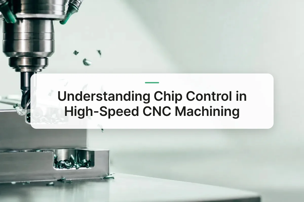
What Is a Chip in CNC Machining and Why Does Chip Control Matter for Precision Work?: chip control CNC machining
A chip is the sheared segment of metal that peels away when a cutting edge deforms and separates material from the workpiece, not incidental scrap. Chip formation happens through shear deformation ahead of the tool tip, the material compresses, yields, and fractures along a shear plane before it curls away as a chip. The shape that results tells a machinist exactly how the cut is behaving.
Chip Types and What They Reveal About the Cut
Machinists generally see three chip forms. Continuous or stringy chips form in ductile materials cut at steady speeds, and they wrap around tooling if nothing breaks them up. Segmented chips show periodic thickness variation, a sign of cyclic shear common in harder alloys. Discontinuous chips break into short pieces on their own, usually the target shape for automated, unattended operation. Chip control CNC machining decisions, insert geometry, feed rate, coolant strategy, are largely about pushing chip formation toward that discontinuous, manageable form.
- Continuous/stringy chips: common in ductile materials at steady speeds; tend to wrap around tooling and fixtures.
- Segmented chips: show periodic thickness variation, typical of cyclic shear in harder alloys.
- Discontinuous chips: break into short pieces on their own, the preferred form for unattended, automated operation.
How Do Different Materials—Titanium, Aluminum, Composites—Produce Different Chip Behaviors?
Material properties dictate chip shape as much as machine settings do. Titanium has low thermal conductivity, so heat concentrates at the cutting edge rather than dissipating into the chip, producing thin, hard segmented chips that accelerate tool wear. Aluminum’s ductility favors long, stringy chips that tangle around tooling and fixtures unless chipbreaker geometry interrupts them. Composites behave differently still, fibers fracture rather than shear, generating abrasive dust and short fragments that pack into flutes and coolant lines.
How Uncontrolled Chips Undermine Precision
Poor chip evacuation causes damage through specific, traceable mechanisms. Wrapped chips can pull a part off-center or snap a tool mid-cycle. Recutting, when a discarded chip passes through the cutting zone again, gouges the surface finish and leaves inconsistent dimensional tolerances. Packed chips block coolant from reaching the cutting edge, spiking local temperature and accelerating tool wear. Each of these directly threatens the dimensional accuracy and surface consistency that precision parts up to 38mm in diameter require. For a deeper look at how shops approach this systematically, see this overview of strategies for managing chip control.
What Are the Main Methods for Chip Control in High-Speed CNC Machining?
Shops manage chip control CNC machining problems with five practical levers: insert geometry, coolant pressure, compressed air, mechanical evacuation hardware, and programming changes. None of these work in isolation, most production floors combine at least three of them on any given job.
When Should You Use Chipbreakers, High-Pressure Coolant, or Blow-Off Nozzles?
Chipbreakers are the first line of defense. They’re geometric features, either molded into an insert or ground into solid carbide tooling, that force the chip to curl tightly and snap into short segments instead of spiraling into a long ribbon. On a Swiss lathe running small-diameter parts, an uncontrolled chip can wrap around the tool or the workpiece and ruin a finish in seconds, so breaker geometry is often chosen before feed rate is even discussed.
High-pressure coolant does two jobs at once. It pulls heat out of the cutting zone, and at higher pressures it physically wedges into the chip formation point to fracture the chip and flush it away from the tool-workpiece interface. This matters most in grooving and deep-hole turning, where chips have nowhere to go except back across the cutting edge.
Blow-off nozzles cover the gap when coolant isn’t practical or desired. Mounted near the spindle or on the Z-axis, they use compressed air to clear chips off the workpiece surface and work-holding fixtures, which keeps dry or near-dry machining processes running without chip buildup fouling the cut. Some machine builders integrate dedicated hardware for this purpose, such as the chip control systems built into modern CNC milling machines.
How Do Chip Conveyors and Chip Carriage Systems Fit Into Your Overall Setup?
Conveyors and carriage systems are the mechanical backbone that moves broken chips out of the machine envelope and into a collection bin, often integrating directly with coolant filtration so fluid gets reclaimed and chips don’t recirculate into the cutting zone. Without this step, even well-formed chips pile up and stall production.
Programming changes are the no-hardware option: adjusting feed rate, depth of cut, or toolpath direction changes chip thickness and shape directly, often solving a chip problem without touching tooling or coolant setup at all.
How Do Chip Control Strategies Differ Between Mills, Lathes, and Multi-Axis Machines?
Chip control CNC machining strategy changes fundamentally with machine architecture, because mills, lathes, and multi-axis platforms each move the tool and workpiece through different cutting geometries.
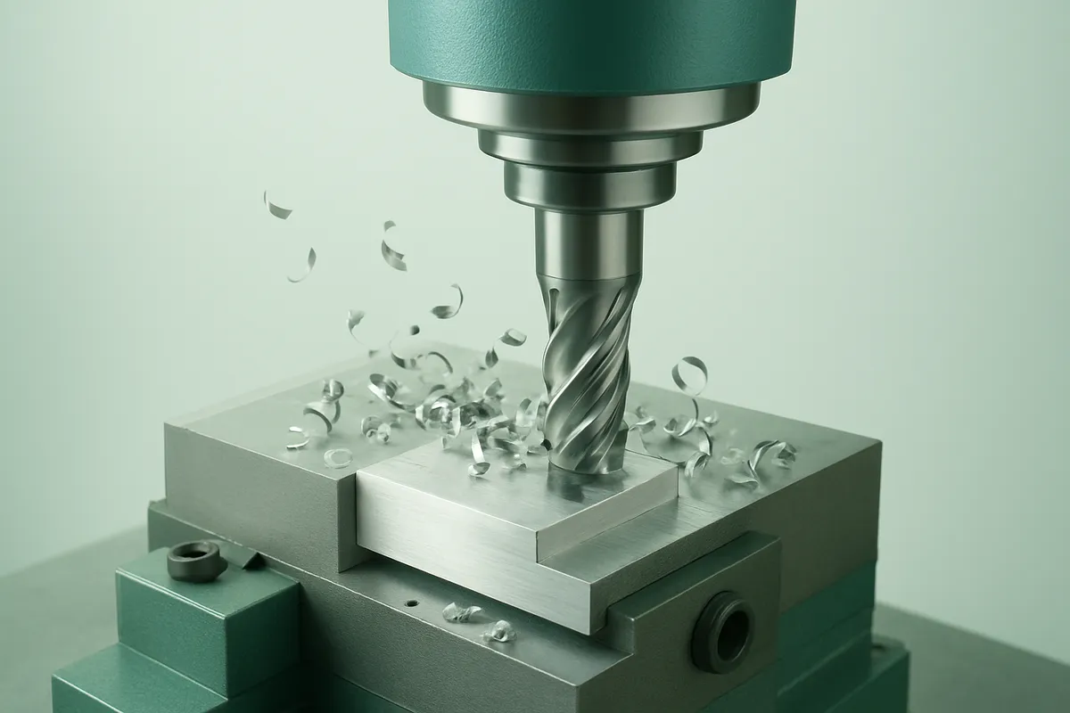
A milling cutter enters and exits the material with every rotation, producing short, intermittent chips rather than one continuous ribbon. Gravity does much of the evacuation work on a horizontal or angled bed, but it needs help, compressed air jets or coolant flow direct chips away from the spindle and off the fixture before the next tool pass buries them under fresh cuttings. Left unmanaged, recut chips gouge the finished surface and accelerate flank wear on the cutter.
Turning presents the opposite problem. A single-point tool holding a fixed depth of cut against a rotating workpiece produces a continuous chip that can spiral for meters if nothing interrupts it. Chipbreaker geometry ground or molded into the insert forces the chip to curl and snap into manageable segments, and grooving or turning-specific feed and speed parameters are tuned to control that fracture point. Get the parameters wrong and the shop ends up with birds’-nest tangles that wrap around the part and stop production.
Multi-axis and mill-turn machines compound both problems at once. As the tool head swivels and the workpiece rotates simultaneously, the chip’s exit path keeps changing, so a clearance geometry that worked at one toolpath angle can trap chips at the next.
What Programming and Process Changes Help Optimize Chip Control for Your Machine Type?
Each platform needs adjustments matched to its motion. On mills, toolpath sequencing that avoids re-cutting chip piles and staggers plunge points reduces recutting damage. On lathes, insert selection and chipbreaker profile drive fragment size more than any other single variable. On multi-axis and mill-turn equipment, simulation-driven clearance checks during programming catch chip-exit conflicts before the first part runs, a step MFG SOLUTION applies across its CNC mill & turn and Swiss lathe operations to keep cycle times predictable on parts up to 38mm in diameter.
What Is the Real Cost-Benefit of Chip Control Systems Versus Manual Chip Management?
Manual chip management looks free on paper but pays out in operator time, inconsistent results, and the occasional missed wrap that damages a part or a spindle. Automated chip control shifts that cost upfront into equipment and programming, trading unpredictable labor drag for a fixed, plannable investment.
The Hidden Cost of Relying on Operators
An operator who stops a machine every few cycles to clear chips isn’t just losing that minute, they’re losing attention on the next part, the next fixture check, the next quality flag. Results also vary by shift and by operator: one person catches a birds-nest wrap before it scores the workpiece, another doesn’t notice until the tool has already snapped. That inconsistency is the real cost, and it rarely shows up as a line item anywhere.
Where Equipment Investment Replaces Labor Risk
Chip conveyors, high-pressure coolant delivery, and toolpaths programmed with deliberate chip-breaking moves all move the cost from reactive labor to planned capital spend. Options generally fall into three tiers:
- Budget-friendly: reprogramming feeds and speeds or adding basic chip breakers to existing tooling, low cost, moderate gain.
- Mid-range: high-pressure coolant systems or blow-off nozzles that clear chips from the cutting zone in real time.
- Premium: full conveyor systems and 5-axis programming that manages chip geometry as a designed part of the cycle, not an afterthought.
How Does Better Chip Control Reduce Downtime and Improve Cost per Part?
Fewer unplanned stops for tool breakage or jam clearing means more of the shift is spent actually cutting metal, and cycle times stay consistent instead of stretching whenever a chip problem forces intervention. That consistency also cuts scrap from recut damage, chips that re-enter the cut and gouge a finished surface. Extend tool life and reduce scrap on a production run of several thousand parts, and the upfront equipment cost gets absorbed fast, directly protecting margin. At MFG SOLUTION, chip control CNC machining decisions are built into process planning up front, part of why orders ship within 3 days without quality surprises on the back end.
How Do You Troubleshoot Chip Control Problems Like Wrapping and Evacuation Blockages?
Troubleshoot chip wrapping and evacuation blockages by isolating the failure point first, then testing one variable at a time, insert, feed, coolant, or conveyor, until the chip shape normalizes.
Diagnosing Chip Wrapping
Wrapping around the tool, workpiece, or turret usually traces back to three culprits. Check insert geometry first, a worn or wrong chipbreaker won’t curl and fracture the chip, so it ribbons out instead. Next, check the feed-to-speed ratio; feed rates that are too low relative to spindle speed produce long, stringy chips that have nothing to break against. Finally, check coolant pressure and nozzle direction, low pressure or a misaligned stream lets chips drift back into the cutting zone rather than clearing away.
Diagnosing Evacuation Blockages
If chips are forming correctly but still piling up, the problem is downstream. Inspect the conveyor belt for wear, misalignment, or overload, a belt running at the wrong speed for chip volume backs up fast. Check the chip pan slope; a pan that’s too flat lets chips settle instead of sliding toward the conveyor. Also inspect coolant filtration, clogged filters reduce flow pressure, which weakens the flushing action that keeps the pan clear.
A Step-by-Step Sequence
- Identify the chip shape actually being produced, long ribbon, tangled bird’s nest, or short comma-shaped segments.
- Compare it against the expected form for that material and operation, steel turning should produce tight C or 9-shaped chips, not continuous strings.
- Adjust one variable at a time: feed rate first, then coolant pressure, then insert geometry, retesting after each change isolates the actual cause instead of masking it.
How Can You Integrate Chip Control Monitoring Into Your Existing CNC Automation and Industry 4.0 Workflows?
Sensor-based monitoring flags abnormal spindle load, torque spikes, or drops in coolant flow that signal a developing chip control problem before it causes a stoppage. Spindle load sensors catch the extra resistance created by wrapped chips; flow sensors on coolant lines catch filtration clogs before pressure drops enough to stop clearing chips. On production floors running certified, high-volume work, the kind MFG SOLUTION manages under IATF 16949 and ISO 13485 process control, that early warning matters more than reactive fixes, since a single undetected wrapping event can scrap a batch mid-run rather than a single part.
Frequently Asked Questions
Can poor chip control damage a finished CNC part?
Yes, recut chips scratch surfaces, dent critical diameters, and can push a tool off its programmed path mid-cut. On thin-wall or tight-tolerance parts, a single trapped chip can cause dimensional drift that fails inspection. This is why process control documentation tracks chip behavior alongside tool wear on precision jobs, especially for medical and automotive components with sub-1% defect tolerances.
Does chip control matter more for high-speed machining than conventional speeds?
Yes, higher spindle speeds generate chips faster and hotter, leaving less margin for error before chips pack against the tool or workpiece. At conventional speeds, an operator often has time to react; at high speed, a chip jam can damage a tool or part within seconds. Coolant pressure and programming adjustments matter more as speed increases.
What’s the difference between chip control and chip evacuation?
Chip control shapes and breaks chips at the cutting edge; chip evacuation removes those chips from the machine once formed. Chip control relies on tool geometry, chipbreakers, and cutting parameters. Chip evacuation relies on conveyors, coolant flow, and blow-off systems. Both have to work together, good control produces chips that evacuation systems can actually clear.
How often should chip conveyors and coolant filters be inspected to prevent chip-related downtime?
Most shops check conveyors and filters at least once per shift, with a deeper inspection weekly. Fine chips and swarf from small-diameter parts clog filters faster than larger turnings, so high-volume small-parts production often needs more frequent checks to avoid coolant contamination and unplanned stoppages.
What role does tool material play in chip control?
Tool substrate and coating affect how heat and friction build up at the cutting edge, which in turn influences chip shape and how quickly an insert wears. Coated carbide inserts tend to shed heat differently than uncoated tooling, changing the chip’s hardness and curl behavior. Matching tool material to the workpiece alloy is as important as chipbreaker geometry when chips form inconsistently.
Conclusion
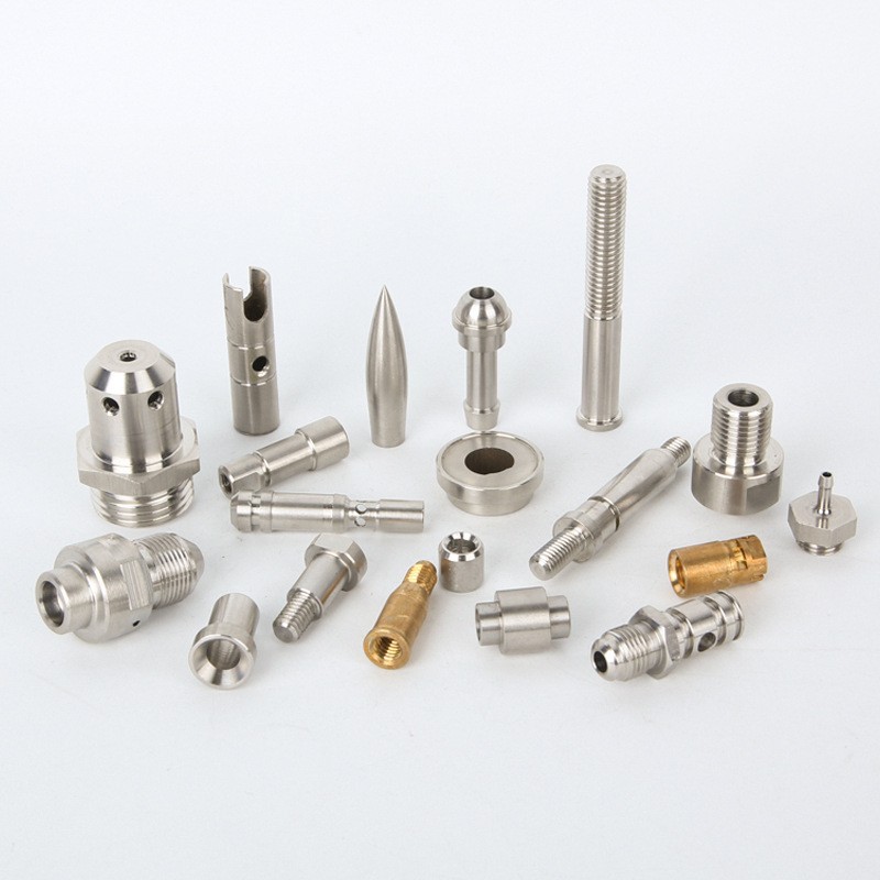
Chip control determines whether a CNC shop hits tight tolerances consistently or fights rework and downtime. The fixes that matter most are unglamorous: matching chipbreaker geometry to the material, dialing in coolant pressure, and inspecting evacuation systems before they fail mid-run. None of this happens by accident, it requires process control that’s tracked and audited, not left to an operator’s judgment call.
For teams sourcing small precision parts up to 38mm, ask any prospective supplier how they document chip and tool-wear control under their ISO 9001:2015 or IATF 16949 process records. MFG SOLUTION builds that documentation into every quote, request one within 8 hours and see how it’s handled on your part.
Recommended Articles
Explore more from our content library: