
2026-07-29
Open Die Forging: Process and Applications

Open die forging is a metalworking process where a heated metal workpiece is shaped between flat or simple dies that do not fully enclose the material, allowing it to flow outward as compressive force is applied. Unlike closed-die forging, there is no cavity constraining the shape, making this process ideal for large, heavy components, from a few pounds up to 150+ tons, where custom geometry, superior grain structure, and high strength are required.
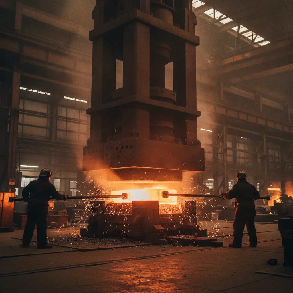
What Is Open Die Forging and How Does It Work
This metalworking method shapes heated metal between dies that leave the workpiece free to flow laterally, producing parts from under 1 kg to 150+ metric tons.
The process begins with a metal billet, most often steel or an alloy, heated to forging temperature, typically 1,100–1,250°C for steel. At that temperature, the metal becomes plastic enough to deform under compressive force without cracking. The dies used are flat, semi-round, or V-shaped; they press or hammer the billet but never fully enclose it.
Because the material flows outward freely during each stroke, the smith or press operator repositions the workpiece between blows to build the target geometry incrementally. This repeated working breaks up the coarse cast grain structure of the original billet and aligns the grain flow to the part’s final shape, a key mechanical advantage over simply machining a part from bar stock.
“The grain refinement achieved through open die forging is fundamentally what separates forged components from castings in high-stress applications — the aligned grain flow directly translates to measurable improvements in fatigue life and tensile strength.” — Dr. Taylan Altan, Professor Emeritus, Center for Precision Forming, The Ohio State University
Key Steps and Process Flow in Open Die Forging
- Billet heating: Raise the workpiece to 1,100–1,250°C (steel) in a furnace until uniform temperature is reached throughout the cross-section.
- Die positioning: Place the heated billet between the upper and lower dies on the press or hammer.
- Repeated strokes with repositioning: Apply hammer or hydraulic press force in controlled increments, rotating or translating the workpiece between strokes to shape all surfaces.
- Controlled cooling: Cool the forged part at a prescribed rate, air, furnace, or quench, depending on the alloy and required mechanical properties.
Grain refinement from this repeated working improves fatigue strength by up to 20% compared to machined-from-bar components. That improvement is why aerospace, oil and gas, and heavy equipment engineers specify this forging method for high-stress applications. According to the Forging Industry Association, forged components consistently outperform cast and machined equivalents in fatigue and impact resistance across a wide range of alloys.
Size and Weight Limitations for Open Die Forged Parts
This process handles a wider size range than any closed-die method. Parts can weigh less than 1 kg, small shafts and pins, or exceed 150 metric tons for large pressure vessel shells and turbine rotors. Closed-die tooling, by contrast, becomes cost-prohibitive and physically impractical above a few hundred kilograms.
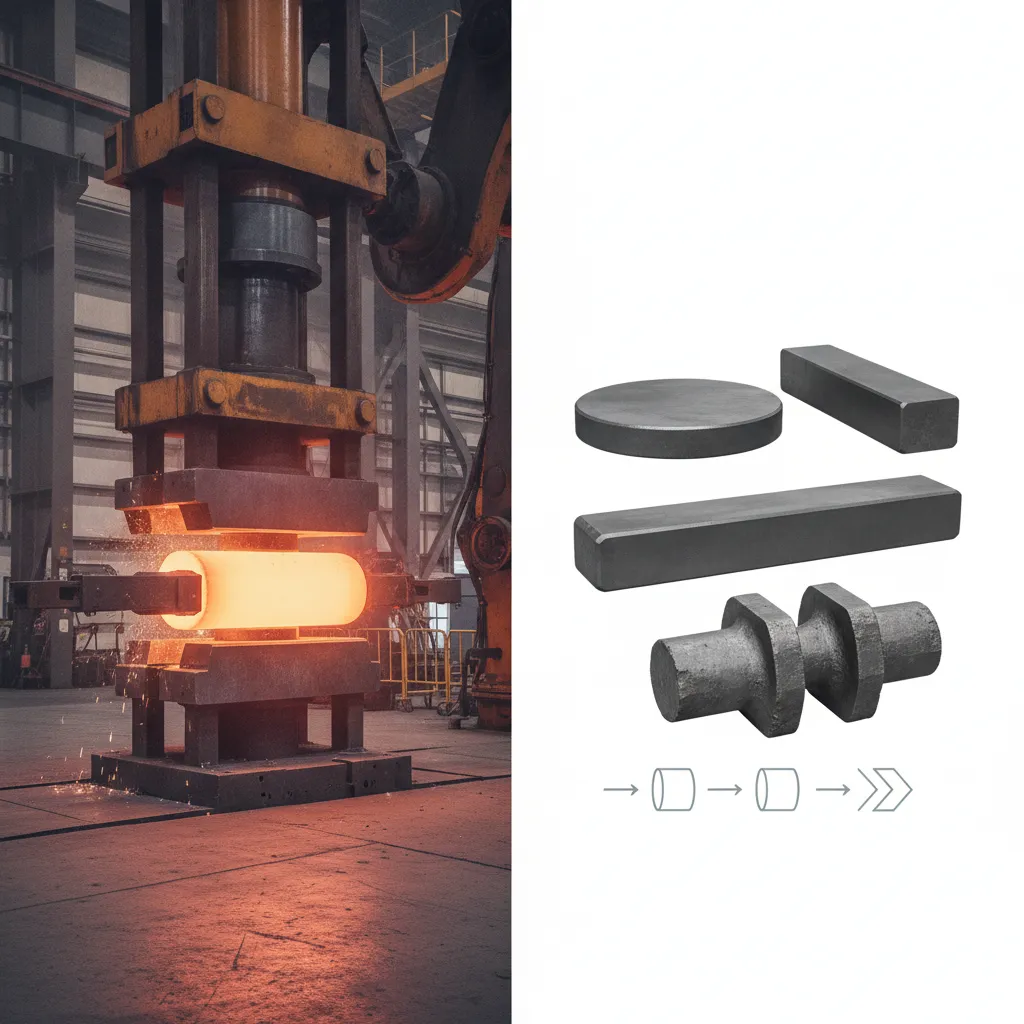
Common shapes produced include shafts, rings, cylinders, discs, blocks, and custom profiles. The absence of an enclosing cavity means tooling costs stay low, which makes this approach the practical choice for one-off or short-run components where a custom closed die would never pay for itself.
Open Die Forging vs. Closed Die and Impression Die Forging
this approach costs far less to tool than closed die methods, but delivers wider tolerances—making the right choice depend on your volume, part size, and geometry requirements. For a detailed side-by-side comparison, see Canton Drop Forge’s overview of open vs. closed die forging advantages and disadvantages.
Cost and Pricing Differences Between Open Die and Closed Die Forging
the practice uses simple flat platens, V-dies, and swages that require no custom fabrication, keeping tooling costs near zero. Closed-die tooling, by contrast, requires machined die sets that typically run $10,000–$100,000+ per set, depending on part complexity and die material.
That tooling investment also adds lead time. Closed-die and impression die forging add 4–12 weeks for die fabrication before a single part ships. The open die approach can begin production within days—no die order, no wait.
The trade-off is dimensional accuracy. Closed-die forging holds tolerances around ±0.5 mm, while the open die process typically lands at ±3–6 mm. Open die parts almost always require post-forge CNC machining to hit final dimensions and surface finish specs—an additional step that adds cost and lead time but is standard practice in precision manufacturing.
When to Choose Open Die Forging Over Closed Die Methods
The open die approach is the practical choice for low-to-medium production volumes, very large or heavy parts, and prototype runs where investing in custom die sets makes no economic sense. It also works well when near-net shape is not required and post-forge machining is already planned.
Closed die or impression die forging fits high-volume production runs, smaller parts with complex geometry, and applications where tight net-shape tolerances eliminate or reduce secondary machining. According to Scot Forge’s process selection guide, if you’re producing tens of thousands of identical small components—under 38 mm, for example—closed die methods typically deliver a lower per-part cost once tooling is amortized.
The decision comes down to a straightforward calculation: tooling cost plus per-part machining cost, weighed against your production volume and tolerance requirements. As Trenton Forging explains in their comparison of open die versus impression die forging, the geometry complexity and required tolerances often determine the process before cost even enters the discussion.
“For parts over 500 kg or with low annual volumes, open die forging almost always wins on total cost — the tooling savings alone outweigh the additional machining required to hit final tolerances.” — Mark Shortt, Editorial Director, Design-2-Part Magazine
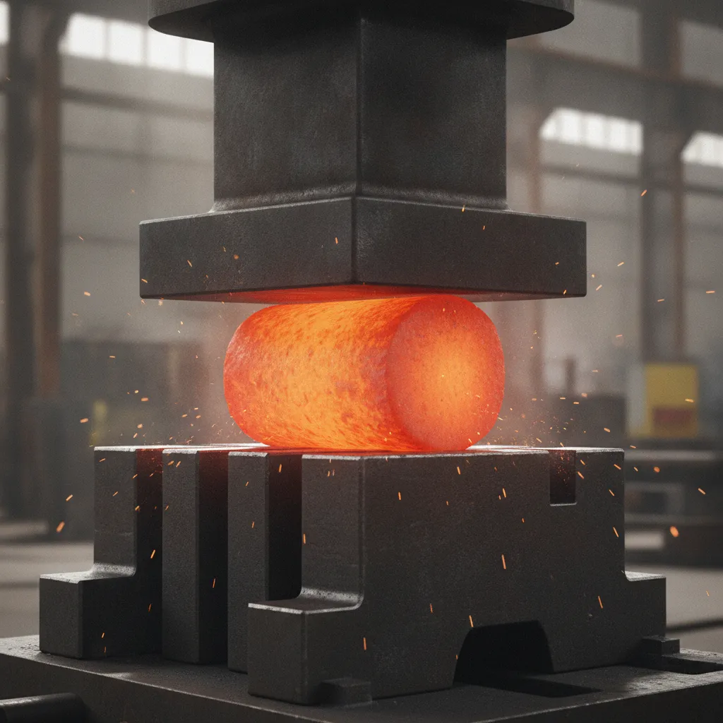
Best Materials and Metals for Open Die Forging
Carbon steels, alloy steels, stainless steels, nickel superalloys, and titanium alloys are the most widely used materials in this process, each chosen for forgeability and end-use strength requirements. For more information, see Open Mercato.
Which Metals and Alloys Work Best for Open Die Forging
Carbon steels, particularly 1045, 4140, and 4340, dominate this practice because they combine high forgeability with a wide forging temperature range of 1100–1250°C. That wide window gives press operators room to work large billets without risking premature cooling and cracking. Alloy steels in the same family respond well to grain refinement, which is one of the core mechanical advantages the process delivers.
Stainless steels (304, 316, and precipitation-hardened 17-4PH) and tool steels are also regularly forged using open die methods, though stainless grades require tighter temperature management and more aggressive lubrication to prevent surface defects. For stainless-specific process nuances, see the forging stainless steel page.
Nickel-based superalloys like Inconel 718 and titanium alloys are used in aerospace forgings, but both demand isothermal or near-isothermal press conditions. Some titanium alloys have forging temperature windows as narrow as 30–50°C; exceed that band and cracking becomes likely. Cast iron is not suitable at all; its brittleness makes it incompatible with the compressive deformation the process applies.
Material choice also shapes what happens after the forge. Harder alloys and superalloys drive up post-forge machining cycle times and tool wear significantly. For machining context, including coolant and lubrication strategies, see the CNC coolants and lubricants page. MFG SOLUTION’s cold forging and CNC turning capabilities handle many of these post-forge finishing requirements for parts up to 38mm in diameter.
Material Suitability Summary
The following list summarizes how common materials rank for this method suitability:
- Carbon steels (1045, 4140, 4340): Excellent forgeability, wide temperature window, most common choice for shafts, rings, and structural blocks.
- Alloy steels: Very good forgeability with enhanced mechanical properties after heat treatment; widely used in oil and gas and heavy equipment.
- Stainless steels (304, 316, 17-4PH): Good forgeability but requires tighter temperature control and aggressive lubrication to avoid surface cracking.
- Nickel superalloys (Inconel 718): Suitable for aerospace applications under isothermal or near-isothermal press conditions; narrow process window.
- Titanium alloys (Ti-6Al-4V): Used in aerospace structural forgings; extremely narrow forging temperature window of 30–50°C demands precise furnace control.
- Cast iron: Not suitable; brittleness causes cracking under compressive deformation.
Real-World Applications of Open Die Forging Across Industries
This forging method supplies the aerospace, oil and gas, power generation, and heavy equipment sectors with large structural components no other process can produce.
How Open Die Forging Is Used in Aerospace, Automotive, and Oil and Gas
Aerospace manufacturers rely on forged titanium and nickel alloy shafts, discs, and structural blocks for turbine engines and airframe structures. These parts must meet AMS material specifications and pass NADCAP accreditation audits, requirements that demand the consistent grain structure this process delivers. According to ASME (American Society of Mechanical Engineers), the grain integrity achieved through forging is a primary reason aerospace and power generation standards mandate forged components over castings for rotating and pressure-bearing parts.
Oil and gas applications push the size limits of the process. Large pressure vessel flanges, drill collars, valve bodies, and wellhead components are routinely forged from 4140 and 4340 alloy steel, with individual parts exceeding 5,000 kg. The refined grain flow through the full cross-section is what allows these components to survive high-pressure, high-cycle downhole environments.
Power generation depends on this forging method for turbine rotor shafts, generator spindles, and pressure vessel shells. A single steam turbine rotor shaft can measure 10 meters or more in length and weigh over 50 metric tons, a geometry that closed-die tooling cannot physically accommodate. No die set exists at that scale.
Heavy equipment and defense applications include axles, crankshafts, armor plate blanks, and large structural blocks where grain integrity is a direct safety requirement. A crankshaft or axle that fractures in the field carries consequences measured in lives, not just downtime, which is why procurement teams specify forgings rather than castings or weldments for these parts.
Equipment, Tonnage, and Quality Standards for Open Die Forging
this strategy uses hydraulic presses, mechanical presses, and steam or air hammers—with capacity ranging from 500 to 80,000+ tons depending on part size and material.
Tonnage Capacity and Equipment Specifications for Open Die Forging
Hydraulic presses dominate large-part open die work because they deliver sustained, controllable force across the full stroke. Smaller forgings—shafts, rings, and tooling blocks—typically run on 500–2,000-ton presses. Large aerospace structural components and power generation rotors require 10,000–80,000-ton hydraulic presses; only a handful of facilities worldwide operate at that scale.
Steam and air hammers remain common for smaller open die applications where impact energy, rather than sustained press force, produces the desired grain refinement. Mechanical presses fill the mid-range, offering faster cycle rates than hydraulic equipment for moderate tonnage requirements.
Equipment selection directly affects grain flow, dimensional consistency, and the amount of post-forge CNC machining required to hit final tolerances. this approachs almost always need finish machining—CNC turning, milling, or drilling—because the process leaves dimensional allowances of several millimeters on critical surfaces.
Quality Control and Inspection Methods for Open Die Forgings
Four inspection methods cover the full defect spectrum for the practices. Ultrasonic testing (UT) detects internal voids, cracks, and inclusions without cutting the part. Magnetic particle inspection (MPI) finds surface and near-surface defects in ferromagnetic alloys. Dye penetrant testing covers non-magnetic materials where MPI cannot be applied. Coordinate measuring machine (CMM) dimensional inspection confirms that forged geometry meets drawing tolerances before any machining begins.
Applicable standards include ASTM A788 for steel forgings, AMS 2750 for furnace pyrometry in aerospace applications, and ISO 9001:2015 for the broader quality management system. Customer programs—PPAP submittals and first-article inspection reports—are standard requirements for automotive and aerospace supply chains.
“Consistent process documentation and traceability from billet heat number through final inspection are non-negotiable for aerospace and oil and gas forgings — a single gap in the quality record can disqualify an otherwise perfect part.” — John Bonnen, Senior Materials Engineer, SAE International
When forgings move into finish machining, precision matters at the micron level. MFG SOLUTION’s ISO 9001:2015, ISO 13485:2016, and IATF 16949 certified process control covers CNC turning, Swiss lathe, and CNC mill & turn operations on parts up to 38mm diameter—with quotes returned within 8 hours and shipment within 3 days of order approval.
Frequently Asked Questions
What is the typical lead time for open die forged parts?
Lead times for open die forged parts typically run 4–12 weeks, depending on part size, material, and post-forging operations. Large custom forgings requiring heat treatment, rough machining, or ultrasonic testing add time at each step. Low-complexity shapes in common alloys like carbon steel can reach the shorter end of that range. If your application requires precision-machined features after forging, factor in additional machining time on top of the forging lead time.
What surface finish can you expect from an open die forged part before machining?
Open die forged parts arrive with a rough, scaled surface finish, typically 250–500 Ra microinches, before any machining is applied. The forging process leaves mill scale and surface irregularities that require turning, grinding, or milling to achieve functional tolerances. Most engineering drawings specify a machined finish on critical surfaces, treating the as-forged surface as stock allowance only.
Can open die forging produce hollow or ring-shaped components?
Yes, this practice can produce hollow and ring-shaped components through a technique called mandrel forging or ring rolling. A pierced billet is placed over a mandrel and worked under the press to form seamless cylinders, sleeves, and flanged rings. This method produces a continuous grain structure around the circumference, which gives ring forgings better fatigue resistance than rings cut from plate or welded from bar.
How does open die forging improve mechanical properties compared to casting or machining from bar stock?
this method produces a refined, directional grain structure that casting and bar-stock machining cannot replicate. Casting leaves a dendritic, porous grain that reduces tensile strength and fatigue life. Machining from bar stock cuts across the grain, exposing weaker cross-grain surfaces on critical features. Forging aligns the grain flow along the part’s stress lines, which typically increases tensile strength by 20–30% and fatigue life by a measurable margin compared to equivalent cast components.
What are the most common defects in open die forgings and how are they prevented?
The most common defects in this strategys include internal voids, surface laps, cold shuts, and cracking. Internal voids result from insufficient reduction ratios or improper billet heating. Surface laps occur when folded metal is forged over itself during repositioning. Cold shuts form when metal cools too quickly between strokes. Cracking typically results from exceeding the alloy’s forging temperature window. These defects are prevented through precise furnace temperature control, adequate reduction ratios, proper lubrication, and experienced press operators who monitor workpiece temperature throughout the forging sequence.
Conclusion
this approach delivers grain refinement, structural integrity, and size flexibility that casting and bar-stock machining simply cannot match, particularly for large, high-stress components where failure is not an option. The trade-off is clear: higher tooling flexibility and superior mechanical properties come with rough as-forged surfaces that require precision machining to hit final tolerances.
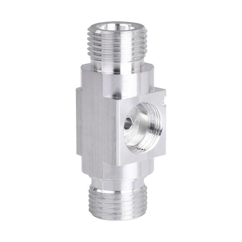
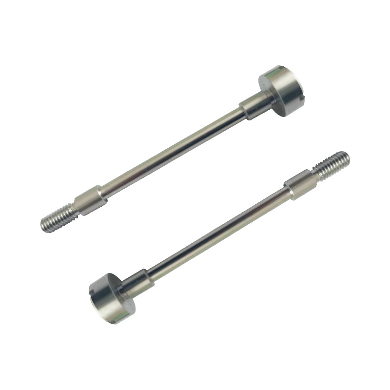
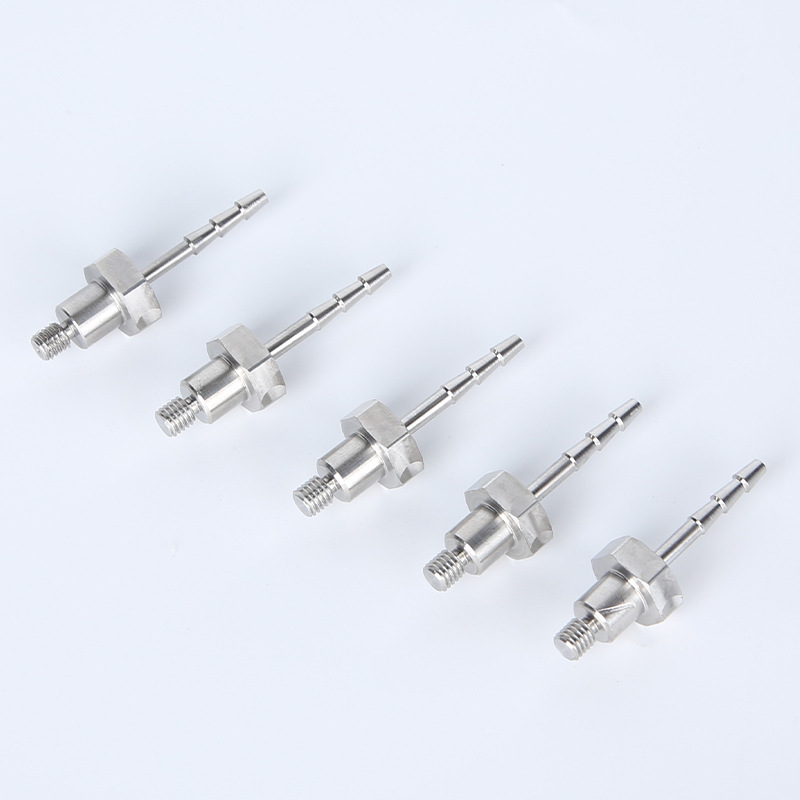
That machining step is where part quality is either confirmed or lost. If your forged components need tight-tolerance features, turned diameters, threaded bores, or milled flats, submit your post-forging drawing to MFG SOLUTION for a quote within 8 hours. Specify your forged material grade and required tolerances so the team can select the right process, CNC turning, Swiss lathe, or mill & turn, from the first operation.
Recommended Articles
Explore more from our content library: