
2026-08-18
How to Machine Small Diameter Parts Successfully

Understanding how to machine small diameter parts is essential. To machine small diameter parts successfully, select the right tooling geometry for your diameter range, dial in high RPM with conservative feed rates, and use collets or guide bushings to minimize workpiece deflection. Parts under 6mm demand Swiss-style turning or micro-turning setups where the cutting zone is supported close to the tool contact point. Chatter, tool breakage, and runout are the three failure modes that kill small-diameter work, each has a specific fix.

What You’ll Need to Machine Small Diameter Parts
Successful small diameter machining requires a Swiss-type or CNC turning center, collet workholding, carbide tooling with positive rake geometry, and high-pressure coolant before cutting begins.
“Workholding is the foundation of small-diameter accuracy. If the part moves, nothing else you do with feeds, speeds, or tooling geometry will save the dimension.” — Dr. John Ziegert, Professor of Mechanical Engineering, Clemson University
Choosing Between Swiss Lathe and CNC Turning for Small Parts
Machine selection is the first decision that determines whether your process will hold tolerance or fail at setup. For parts under 12mm diameter at production volumes, a Swiss-type lathe is the correct choice, the guide bushing supports the bar stock directly at the cutting zone, eliminating deflection that would otherwise ruin dimensional accuracy. CNC turning centers handle the 12–38mm range efficiently and offer faster changeover for moderate batch sizes. Manual lathes are only practical for single one-off parts where tolerance requirements are relaxed.
When learning how to machine small diameter parts at scale, matching the machine type to the diameter range cuts scrap rates significantly. MFG SOLUTION runs dedicated Swiss lathe and CNC turning operations across this full diameter range, up to 38mm, with 20 automatic lathes and 5-axis CNC machines available for production runs.
Collets vs. Chucks: Workholding Accuracy Compared
Collets hold tolerances to ±0.005mm and keep runout low enough for diameters under 6mm. Three-jaw chucks introduce runout that exceeds acceptable limits at those sizes, avoid them for any part below 6mm. For Swiss-type setups, the guide bushing adds a second layer of support beyond the collet, which is why it remains the standard workholding method for the smallest diameters.
According to the Society of Manufacturing Engineers (SME), proper workholding selection is one of the most critical factors in achieving repeatable tolerances on small-diameter turned parts, with collet-based systems outperforming jaw chucks by a factor of three or more in runout control at diameters below 6mm.
Before the first cut, assemble the following minimum tooling:
- High-speed steel or carbide insert tools with positive rake geometry to reduce cutting forces on thin stock
- Boring bars with an L/D ratio under 4:1 to prevent bar deflection and chatter
- A dial indicator for runout verification at setup, check before every production run
Coolant selection is not optional for small diameters. Parts under 3mm require either high-pressure coolant at 500–1,000 PSI or minimum quantity lubrication (MQL) to prevent chip packing in the cutting zone, packed chips at this scale break tools and ruin surface finish instantly. Review compatible CNC coolants and lubricants for your specific material before starting.
Inspection equipment must be on hand before production begins, not after. You need an optical comparator or CMM capable of resolving ±0.001mm, plus a surface finish profilometer to verify Ra values against your drawing callouts. Measuring after the fact without the right equipment means scrapping parts you could have caught at first article.
How to Machine Small Diameter Parts: Step-by-Step Setup and Cutting Parameters
Machine small diameter parts by anchoring every parameter to surface speed, not raw RPM, then sequence rough, finish, and measure in strict order.
Surface speed (SFM or m/min) stays constant across materials; RPM is what you calculate from it. A 3mm aluminum part needs 15,000–20,000 RPM to hit a target surface speed near 150–200 m/min. Drop to 6mm stainless steel and you target 8,000–12,000 RPM; 12mm mild steel runs 3,000–5,000 RPM. Let diameter drive the math, not habit.
“The most common mistake machinists make on small-diameter work is programming RPM from habit rather than calculating it from surface speed. At 3mm, that habit will break tools and ruin parts within the first few cycles.” — Dr. Yusuf Altintas, Professor and Director, Manufacturing Automation Laboratory, University of British Columbia
Setting RPM and Feed Rates for Diameters Under 6mm
For parts under 6mm, limit depth of cut to 0.05–0.15mm per pass and feed rate to 0.01–0.03mm/rev. Exceeding these values deflects the workpiece before the cutting edge engages, and on stock this thin, deflection and breakage happen in the same moment.
Tool geometry is equally critical. Positive rake angles of 10–15° reduce cutting forces on thin stock. Sharp edges are non-negotiable: a dull tool pushes small-diameter stock sideways instead of shearing it. Replace or re-grind before any finish pass.
Material behavior changes the equation. Stainless steel work-hardens rapidly, so cuts must be continuous, any dwell lets the surface harden ahead of the tool. Aluminum demands high rake angles and polished flutes to prevent built-up edge, which ruins surface finish and dimensional accuracy.
Roughing vs. Finishing Pass Strategy for Small Parts
Follow this five-step sequence every time you machine small diameter parts:
- Verify runout below 0.005mm before the first cut. Use a dial test indicator at the collet face, any runout above this threshold amplifies into chatter and dimensional error at small diameters.
- Rough at 60% of finish RPM with a higher feed rate. This removes bulk material with lower heat buildup and reduced tool stress.
- Leave 0.1–0.2mm stock on the diameter for the finish pass. Removing too little stock in finishing prevents the tool from cutting cleanly; too much risks deflection.
- Run the finish pass at full RPM with minimum feed (0.01mm/rev or lower). This produces the surface finish and dimensional accuracy the part requires.
- Measure immediately after tool retract, before the part cools fully. Thermal contraction on small parts can shift a dimension by several microns within minutes of cutting.
At MFG SOLUTION, setups for parts up to 38mm diameter follow this same sequence across Swiss lathe and CNC turning operations, with runout checks logged as part of the documented process control required under ISO 9001:2015 and IATF 16949 certification.
Control Part Deflection and Achieve Tight Tolerances
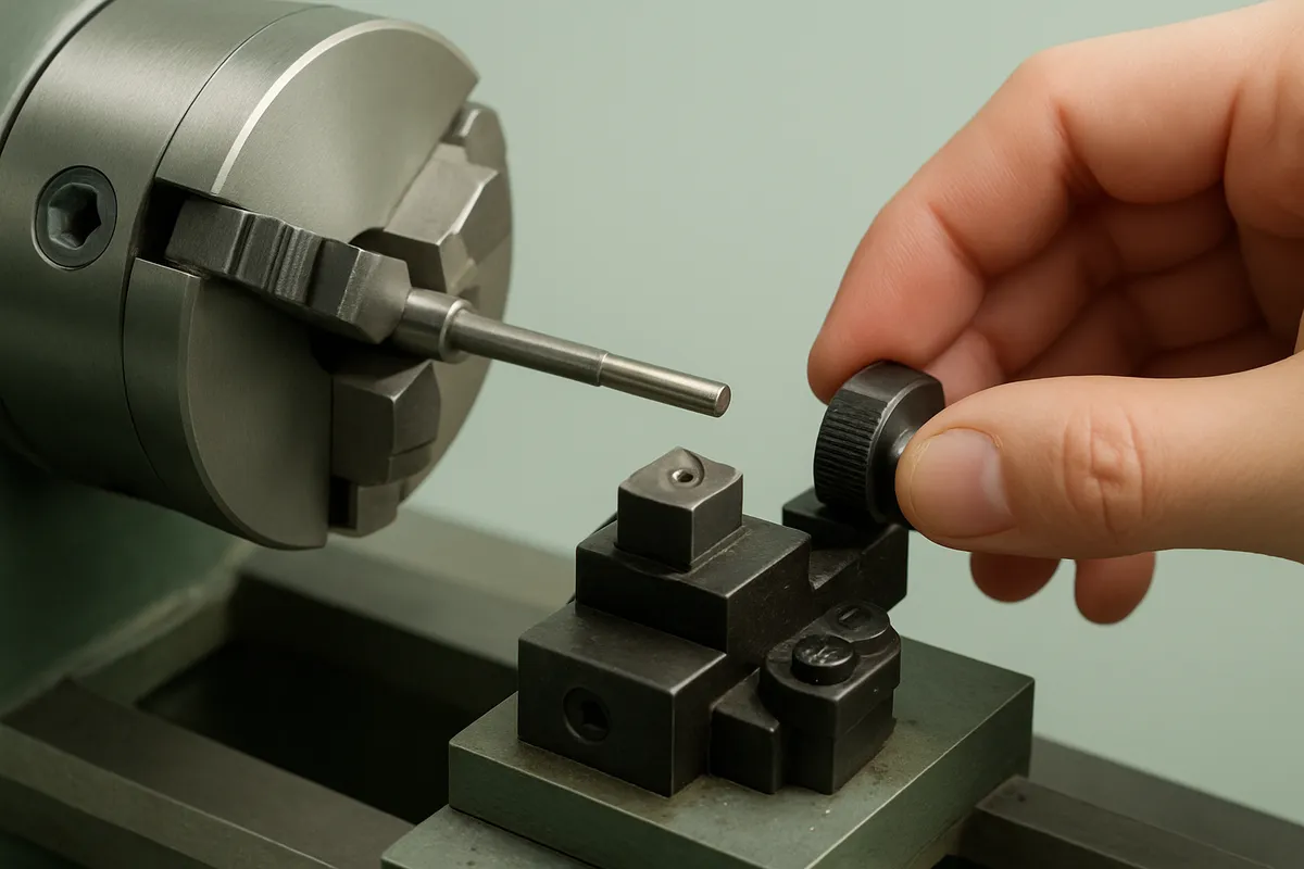
Deflection is the primary reason small diameter parts fail to hold tolerance, and the right support method cuts that error by a factor of 8 or more.
The physics are straightforward. A 3mm diameter steel bar deflects approximately 8 times more than a 6mm bar under the same cutting force, because deflection scales with the inverse fourth power of diameter. Any L/D ratio above 3:1 demands active workpiece support, without it, the bar bends away from the tool, producing taper, chatter, and out-of-round profiles. Understanding this is central to how to machine small diameter parts reliably at production volumes.
According to NIST’s Manufacturing Program, dimensional instability caused by workpiece deflection accounts for a significant share of out-of-tolerance rejections in precision small-part turning, particularly for parts with length-to-diameter ratios exceeding 4:1.
When to Use a Guide Bushing vs. a Steady Rest
On Swiss-type lathes, the guide bushing supports the bar within 1–2mm of the cutting zone. That proximity virtually eliminates deflection for parts up to 32mm long, making Swiss turning the preferred process when diameter is under 20mm and length-to-diameter ratio is high. MFG SOLUTION’s Swiss lathe machines hold ±0.005mm routinely on these geometries.
On conventional CNC lathes, a steady rest is the practical alternative. Position it within 3 times the workpiece diameter of the cutting point. For diameters under 6mm, use bronze or roller-type rests, they apply less drag force and reduce the risk of marking the surface. CNC turning with a collet chuck holds ±0.010mm; a manual lathe with a standard three-jaw chuck struggles past ±0.025mm on small diameters. For a full breakdown of how these methods interact with tolerance stackup, see our precision tolerance stackup guide.
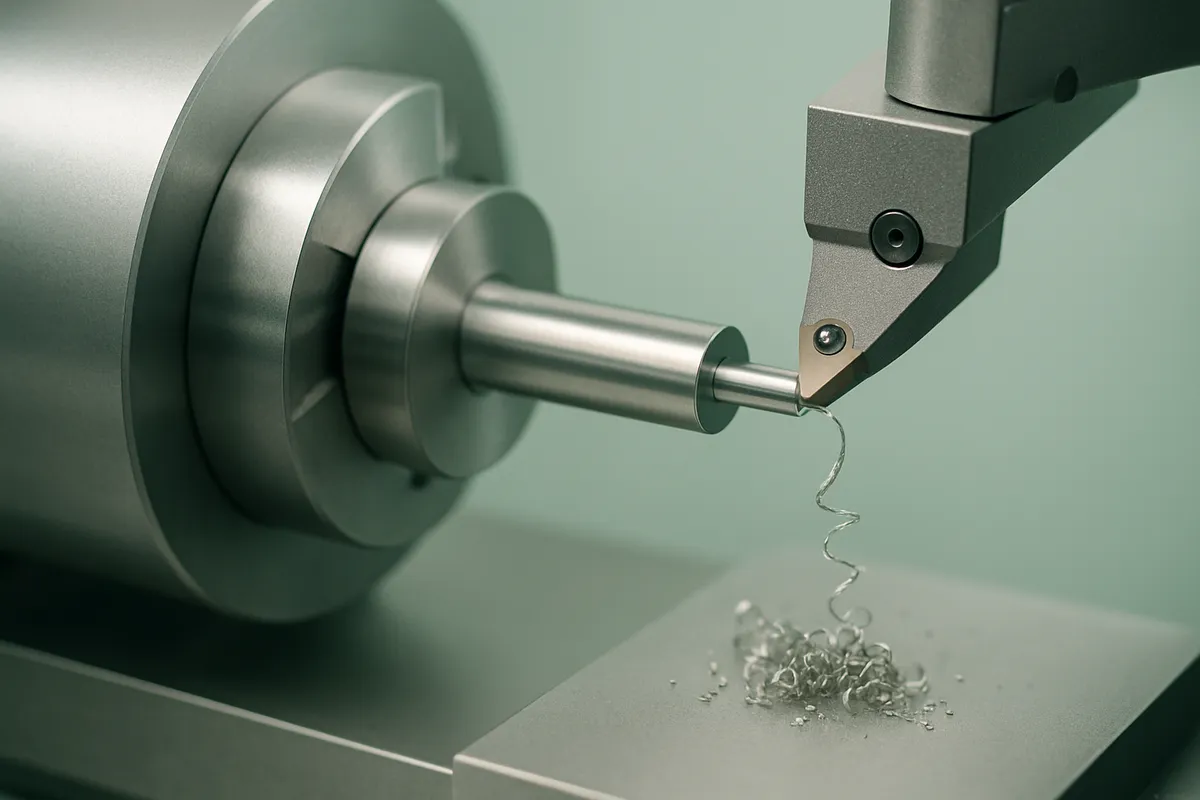
Surface finish targets of Ra 0.4–0.8µm are achievable with sharp carbide inserts running at the correct surface feet per minute for the material, typically 300–500 SFM for steel. Dull tooling or incorrect SFM pushes Ra above 1.6µm and introduces micro-burrs on bore edges. See our surface finish CNC machining page for finish verification methods and measurement standards.
Troubleshoot Common Failures: Chatter, Tool Breakage, and Poor Surface Finish
Most failures when machining small diameter parts trace back to three root causes: chatter vibration, tool breakage, or surface finish defects, each with a distinct fix.
Diagnosing Chatter vs. Tool Wear vs. Workpiece Deflection
Chatter shows up as regular wave patterns on the machined surface. The primary causes are excessive length-to-diameter (L/D) overhang, worn spindle bearings, or an RPM that hits a resonance frequency. Reduce RPM by 10–15%, increase feed rate slightly, or shorten tool overhang, whichever matches your diagnosis.
Part deflection is frequently mistaken for tool wear. If a turned part measures larger at the free end than at the chuck, deflection is the cause. Add a steady rest or tailstock support, or reduce depth of cut, do not swap the tool first.
Built-up edge (BUE) on aluminum and stainless steel causes tearing and a degraded Ra value. Fix it with higher surface speed, a sharper tool geometry, and flood coolant. Never run aluminum dry, the material welds to the cutting edge within seconds at typical spindle speeds.
Diameter variation greater than 0.010mm around the circumference points to runout, not a cutting problem. Seat the collet correctly and check spindle runout with a test indicator before adjusting any cutting parameters.
Fixing Tool Breakage on Sub-3mm Diameters
Tool breakage on sub-3mm diameters is almost always caused by chip packing or re-cutting chips, not excessive cutting force. Increase coolant pressure or switch to minimum quantity lubrication (MQL) to clear chips from the flutes before they compact.
“Chip evacuation is the dominant failure mechanism in micro-drilling and sub-3mm turning. Machinists who solve the chip problem solve 80% of their tool breakage problems at once.” — Dr. Tugrul Özel, Professor of Industrial and Systems Engineering, Rutgers University
- Check coolant pressure first. For drills and end mills under 3mm, direct high-pressure coolant at the cutting zone or use through-tool coolant if the spindle supports it.
- Switch to MQL if flood coolant cannot reach the cut. MQL delivers a fine oil mist that lubricates the flute path and reduces chip adhesion without the mess of full flood.
- For 3–6mm tools, examine depth of cut and rake angle. Breakage in this range typically signals an aggressive depth of cut or a rake angle mismatched to the workpiece material, reduce axial depth by 20% and verify the tool geometry matches the material specification.
At MFG SOLUTION, parts down to the smallest diameters in our 38mm-and-under range run on Swiss lathe and automatic lathe equipment specifically configured for chip control, a process detail that eliminates the majority of sub-3mm breakage events before they reach production.
Scale Small Diameter Machining for Production Volumes
Transitioning from prototype to production on small diameter parts requires automation, cycle time discipline, and statistical quality control from the first batch.
The decision of when to switch machining methods matters most at this stage. If a part’s length exceeds 3x its diameter and tolerances are tighter than ±0.015mm, Swiss-type machining pays back its setup cost at volumes above 500 pieces. Below that threshold, CNC turning with live tooling often delivers better economics. According to ASME’s precision machining resources, statistical process control implemented from the first production batch reduces long-run scrap rates by 30–50% on tight-tolerance small-diameter parts. For more on threading small diameter parts at production scale, see our CNC threading optimization guide.
Cycle time drops significantly when you overlap drilling and turning operations using live tooling rather than running them sequentially. Pre-setting tools offline eliminates on-machine setup time, and gang tooling layouts, where multiple tools are fixed in a single row, are particularly effective for parts under 10mm diameter.
Bar Feeder Setup for Continuous Small Part Production
Automatic bar feeders on Swiss-type lathes enable lights-out production for parts under 32mm diameter, with cycle times of 30–90 seconds per part achievable on simple geometries. A single operator can oversee multiple spindles simultaneously, cutting direct labor cost per piece by 40–60% compared to manual loading.
For a full walkthrough of Swiss lathe configuration for high-volume runs, refer to our Swiss machining implementation guide.
Quality control at volume requires more than end-of-run inspection. Implement statistical process control (SPC) with Cpk targets above 1.33 for critical diameters, and check every 10th part minimum on high-volume runs. MFG SOLUTION applies this SPC protocol across its 20 automatic lathes, backed by IATF 16949 and ISO 9001:2015 certification, so every production batch ships with documented process data, not just a pass/fail stamp. Learning how to machine small diameter parts at scale means building these controls into the process from day one, not retrofitting them after a quality escape.
Frequently Asked Questions
What is the minimum diameter that a CNC lathe can machine accurately?
Most CNC lathes can accurately machine diameters down to 0.5mm, though Swiss-type lathes regularly hold tolerances on parts as small as 0.3mm. Accuracy at these sizes depends heavily on spindle runout, tooling rigidity, and material selection. Conventional CNC turning becomes less reliable below 3mm diameter because workpiece deflection increases sharply, Swiss machining, which supports the part at the cutting zone via a guide bushing, is the preferred method for anything under 3mm.
How do you prevent tool breakage when drilling small diameter holes?
Use peck drilling cycles, reduce feed rate by 30–50% compared to standard drilling, and apply high-pressure coolant directed at the cutting edge. Small drills, anything under 3mm, break primarily from chip packing and heat buildup, not from cutting force alone. Choosing carbide over high-speed steel and keeping drill depth below 3× diameter per peck significantly extends tool life. Spindle speed should increase as diameter decreases to maintain correct surface footage.
What materials are easiest to machine at small diameters?
Free-machining brass (C36000) and aluminum alloys (6061-T6, 2011) are the easiest materials to machine at small diameters because both produce short, breakable chips and generate low cutting forces. Stainless steel and titanium are significantly harder to manage, work hardening and chip adhesion increase tool wear and deflection risk. For medical and automotive applications where stainless is required, MFG SOLUTION selects process parameters and tooling geometry specifically optimized for small-diameter stainless turning.
How does Swiss machining differ from conventional CNC turning for small parts?
Swiss machining feeds the workpiece through a guide bushing that supports it directly at the cutting point, eliminating deflection, conventional CNC turning holds the part only at the chuck, leaving the cutting zone unsupported. This makes Swiss lathes far more accurate for long, slender parts where the length-to-diameter ratio exceeds 4:1. Swiss machines also perform multiple operations (turning, drilling, threading, milling) in a single setup, which reduces handling errors and cycle time on complex small parts under 38mm diameter.
What tolerances are achievable when machining parts under 5mm in diameter?
On parts under 5mm in diameter, Swiss-type CNC lathes routinely achieve dimensional tolerances of ±0.005mm (±0.0002 in) and surface finishes of Ra 0.4 µm or better. Achieving these figures requires temperature-controlled machining environments, sharp carbide tooling, and rigorous in-process measurement. Looser tolerances of ±0.01–0.02mm are standard for less critical features. MFG SOLUTION holds these specifications under ISO 9001:2015 and IATF 16949 process controls, with every step tracked and documented for full auditability.
Conclusion
Machining small diameter parts comes down to three decisions made before the first cut: choosing the right process (Swiss lathe for slender parts, CNC turning for shorter geometries, mill-turn for complex features), selecting material that won’t work-harden or deflect under load, and setting up workholding and tooling that eliminate vibration at the source. Getting any one of these wrong multiplies scrap rates and tool costs across an entire production run.
If your parts fall under 38mm in diameter and your current supplier is quoting 4–6 week lead times, submit your specifications to MFG SOLUTION, you’ll have a detailed quote within 8 hours and can evaluate process selection, tolerances, and cost before committing to a run.
Recommended Articles
Explore more from our content library: