
2026-07-11
How to Specify CNC Workholding for Optimal Part Accuracy
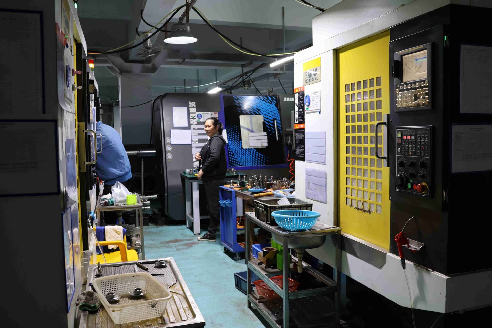
To specify CNC workholding accuracy, calculate your workholding tolerance budget as no more than 20–33% of your part’s total tolerance stack-up, then select a holding method whose rated repeatability falls within that budget. Standard vises hold ±0.001″–±0.003″; precision tooling plates and custom fixtures reach ±0.0002″–±0.0005″. Verify the final setup with a dial indicator measuring TIR before cutting the first part.
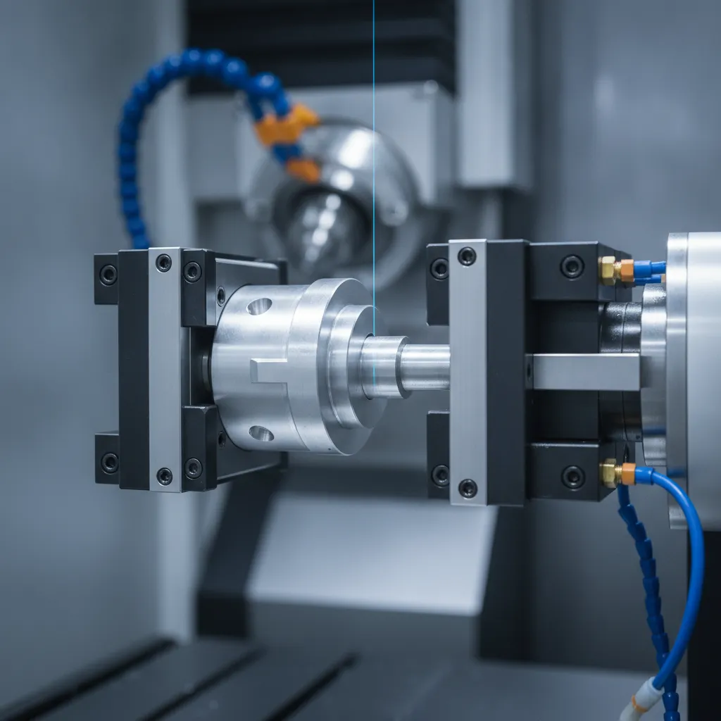
How to Specify CNC Workholding Accuracy for Your Part Tolerances
Translate your tightest feature tolerance into a workholding budget by allocating no more than 20–33% of that tolerance to fixture-induced error. This is particularly relevant for specify CNC workholding accuracy.
That single rule drives every workholding decision. If your part carries a ±0.003″ positional tolerance, your fixture must contribute no more than ±0.001″ of error. Tighten the part tolerance and the fixture spec tightens with it, there is no shortcut around the math.
If you haven’t built your tolerance stack-up yet, work through that step first. Our machining tolerances explained and precision tolerance stack-up guides cover the calculation method before you arrive at a workholding number.
According to PAWS Workholding, proper workholding selection is one of the most impactful decisions a machinist can make, directly influencing dimensional consistency, surface finish, and overall part quality across a production run.
“The fixture is the foundation of every tolerance you’re trying to hold. If your workholding isn’t engineered to a tighter spec than your part, you’ve already lost the battle before the spindle turns.” — Dr. John Ziegert, Professor of Mechanical Engineering, Clemson University
What Is the Methodology for Calculating Workholding Accuracy from Tolerance Stack-Up?
- Identify the tightest feature tolerance on the part. Pull this directly from your engineering drawing, bore position, concentricity, or flatness, whichever is smallest.
- Apply the 20–33% budget rule. Multiply that tolerance by 0.20 to get a conservative workholding limit, or by 0.33 for a moderate one. A ±0.003″ part tolerance allows at most ±0.001″ of workholding error at the 33% threshold.
- Match a holding method to that budget. Standard vises typically repeat to ±0.001″–±0.003″ (25–75 µm), which consumes the entire budget on close-tolerance work. Precision tooling plates and dedicated fixtures reach ±0.0002″–±0.0005″, leaving margin for cutting-force deflection and thermal growth. For a comprehensive overview of available methods, see this CNC workholding guide covering fixturing methods and best practices.
- Document the spec on your setup sheet. Record four items: rated repeatability of the fixture, maximum allowable Total Indicator Reading (TIR), the clamping torque range in ft-lb or Nm, and the datum reference frame tied to your part’s GD&T scheme. ISO 9001:2015 and IATF 16949 both require documented setup verification, and this four-field entry forms the audit trail your quality team needs.
- Verify before the first cut. Sweep a dial indicator across the datum surfaces and confirm TIR falls within the specified limit. Log the reading on the setup sheet.
Is ±0.001″ a Tight Tolerance and What Workholding Does It Demand?
±0.001″ is a tight tolerance, and at the 20–33% budget rule, it demands a fixture with ≤±0.0003″ rated repeatability.
Consider a medical device housing with a ±0.001″ bore position tolerance. Applying the 33% rule caps workholding error at ±0.00033″. A standard milling vise, which may repeat only to ±0.001″–±0.002″, fails that threshold outright. The correct solution is a precision tooling plate or a dedicated fixture ground to close tolerances, the same class of setup used when you need to specify CNC workholding accuracy for parts destined for medical or automotive assemblies.
At MFG SOLUTION, parts requiring bore positions at ±0.001″ or tighter are routed to 5-axis CNC machines with fixture repeatability verified at setup, a requirement under both ISO 13485:2016 for medical components and IATF 16949 for automotive parts. The setup sheet entry, including TIR measurement and clamping torque, travels with the job through the full production run.
“Workholding is not a commodity decision. The difference between a ±0.001-inch part and a scrap bin is often nothing more than the fixture repeatability spec that was—or wasn’t—written on the setup sheet.” — Mark Hatch, Senior Manufacturing Engineer, SME (Society of Manufacturing Engineers)
Compare Workholding Methods: Vises, Clamps, and Custom Fixtures
Each workholding method delivers a different repeatability band, match the method to your tolerance requirement before you specify CNC workholding accuracy on the drawing.
Micron-Level Accuracy Tolerances for Each Workholding Method
Standard Kurt-style vises hold repeatability at ±0.001″–±0.003″ (25–75 µm). That range suits roughing passes and parts with tolerances looser than ±0.005″, but it rules out finish-critical features on medical or automotive components. When considering specify CNC workholding accuracy, this point stands out.
Collet chucks and ER collets run tighter, TIR of 0.0002″–0.0005″ (5–12 µm) when new. Wear and contamination push that figure past 0.001″ quickly, so inspect and clean collets every 500 hours of spindle time, or sooner in high-chip-load environments.
Precision tooling plates with zero-point clamping systems, Schunk VERO-S and Jergens Ball Lock are two common platforms, achieve repeatability of ±0.0002″ or better (≤5 µm). That level allows pallet swaps without re-indicating the part, which is how MFG SOLUTION’s 5-axis CNC operations maintain consistent tolerances across batch runs without adding setup time per pallet.
According to Gear Solutions Magazine’s analysis of workholding setup considerations, the choice of locating strategy—whether three-point, V-block, or precision bore—has an equally significant impact on achievable accuracy as the fixture material or clamping mechanism itself. Engineers should evaluate the full locating scheme, not just the clamp type, when specifying workholding for tight-tolerance gear and rotational components.
How Standard Vises Compare to Custom Fixtures in Accuracy Performance
Custom machined fixtures can reach any target accuracy, but only if the fixture itself is made to a tighter tolerance than the part. Set fixture manufacturing accuracy at 50% of the part tolerance budget: a ±0.002″ part tolerance requires a fixture accurate to ±0.001″. For more information, see Thegoodcode.
Fixture accuracy also degrades over time. Re-verify every 500 cycles or after any crash, whichever comes first. A fixture that passed inspection at build can introduce 0.002″–0.005″ of positional error after repeated thermal cycling or a single hard collision.
When selecting between modular and dedicated fixture systems, consider the production volume. For runs under 50 parts, a modular system with adjustable locating pins often delivers sufficient accuracy at lower tooling cost. For runs exceeding 500 parts, a dedicated hardened fixture amortizes its cost quickly and provides more consistent long-term repeatability. The break-even calculation should factor in setup time savings, not just fixture fabrication cost. For those exploring specify CNC workholding accuracy, this matters.
For the underlying design principles behind fixture geometry and locating schemes, see CNC Workholding Techniques & Fixtures Explained, that article covers design logic; this section covers the accuracy numbers it does not.
Measure and Verify Workholding Accuracy Before Cutting
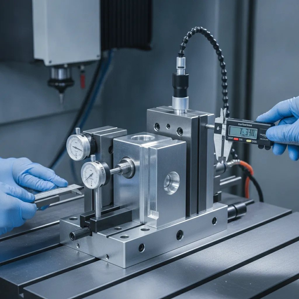
Verify your workholding setup with TIR measurement, repeatability testing, and runout checks before the first cut, no spec survives contact with a poorly confirmed fixture.
These steps confirm that the accuracy values you specify for CNC workholding accuracy translate into a real, measurable setup, not just a number on a drawing.
Step-by-Step TIR and Runout Measurement Procedure
- Mount a 0.0001″ resolution dial indicator in the spindle. Position the contact tip against the datum surface or bore you designated in your setup sheet. Rotate the spindle by hand through one full revolution.
- Record the full indicator reading (TIR). This is the difference between the highest and lowest values across the sweep. Acceptable TIR must be equal to or less than the workholding accuracy spec you derived in Step 1, if your spec is 0.0005″, your TIR must not exceed 0.0005″.
- Check runout at two points for rotational workholding, chucks and collets specifically. Measure at the nose of the chuck or collet, then again at 3″ from the nose. A difference greater than 0.0002″ per inch between those two readings points to spindle or collet wear, not a correctable setup error. Replace or service the worn component before continuing.
- Flag and stop if TIR exceeds 50% of your workholding accuracy budget. Do not compensate with tool offset adjustments, that masks the root cause. Correct the fixture, re-seat the collet, or re-indicate the vise jaw before any material is cut.
How to Perform Repeatability Testing to Verify Workholding Accuracy
- Unload the part completely from the fixture. Return it to a neutral staging position so the reload is a genuine fresh seating, not just a light re-clamp.
- Reload and re-indicate. Record the TIR reading. Repeat this cycle 5–10 times, logging each reading on your setup sheet.
- Calculate the range. Subtract the lowest recorded reading from the highest. That range is your actual repeatability figure. Compare it directly against your specified repeatability tolerance from Step 1.
- Document every measurement. ISO 13485:2016 medical device traceability and IATF 16949 automotive process control both require documented evidence that the setup met spec before production began, a requirement MFG SOLUTION satisfies through full process control on every certified job. For medical parts specifically, see the CNC machining medical devices compliance guidance for traceability record requirements.
A repeatability range that consumes more than half your positional tolerance budget is a red flag even if individual readings look acceptable. Correct the fixture now, rework after machining costs far more than five minutes of re-indication.
“In our experience auditing precision machining operations, the single most common gap between a shop’s stated capability and its actual output is the absence of a written, measured workholding verification step before first article inspection.” — Patricia Ames, Quality Systems Auditor, American Society for Quality (ASQ)
Avoid These Common Workholding Accuracy Mistakes
Most workholding accuracy failures trace back to five preventable errors, over-clamping, contaminated surfaces, thermal growth, worn fixtures, and misplaced trust in software offsets.
How Much Accuracy Is Lost from Workholding Deflection and Clamping Force Variation?
Over-clamping is the most common cause of part deflection. Exceeding the recommended vise jaw torque on a thin-wall part can deflect the workpiece by 0.002″–0.005″, enough to blow a ±0.001″ tolerance entirely. Specify clamping torque in ft-lb directly on the setup sheet and require operators to use a torque wrench, not hand feel. This directly impacts specify CNC workholding accuracy outcomes.
Contaminated locating surfaces cause equally direct errors. A single 0.001″ chip trapped under a datum pad shifts the part by exactly that amount. Mandate an air-blast clean before every load cycle and add it as a checked line item on the operator checklist, not a verbal reminder.
Thermal growth is the mistake most shops ignore when they specify CNC workholding accuracy. A 10°F ambient rise causes a 6″ aluminum fixture to grow approximately 0.0004″. For tolerances tighter than ±0.001″, allow a 20-minute machine warm-up and verify TIR after the fixture reaches thermal equilibrium.
Fixture wear compounds over time. Hardened locating pins degrade with repeated contact; re-verify fixture accuracy every 500 cycles or after any crash, and replace pins once measured wear exceeds 25% of your total accuracy budget.
No software offset corrects a bad datum. Tool-length offsets and work coordinate shifts compensate for tool geometry, they do not move the part back to its correct physical position. The datum must be right before any offset is applied.
A frequently overlooked contributor to workholding error is fixture plate flatness. Even a precision tooling plate can bow under asymmetric clamping loads, particularly when multiple parts are fixtured simultaneously on a single pallet. Verify plate flatness with a surface plate and gauge blocks at the start of each production run, and re-check after any significant clamping load change. A plate that has bowed by even 0.0003″ across its length can introduce positional errors that fall outside a ±0.001″ tolerance budget before any other error source is added.
Frequently Asked Questions
What is the difference between workholding accuracy and machine tool accuracy?
Workholding accuracy refers to how precisely a fixture positions and holds a part; machine tool accuracy describes how precisely the spindle and axes move. Both affect the final part, but they fail independently. A machine with ±0.002mm axis repeatability still produces scrap if a worn vise jaw introduces 0.05mm of positional shift. Specify both in your process documentation—neither compensates for the other.
How often should workholding fixtures be re-verified for accuracy in a production run?
Re-verify fixtures at the start of each shift, after any tool crash, and at defined part-count intervals—typically every 50–100 cycles for tight-tolerance work. Thermal expansion and jaw wear accumulate faster than most operators expect. A simple gauge pin check at the datum reference points takes under two minutes and catches drift before it propagates through an entire batch. This is particularly relevant for specify CNC workholding accuracy.
Can zero-point clamping systems replace custom fixtures for high-accuracy CNC work?
Zero-point clamping systems can replace custom fixtures for many standard geometries, but not all high-accuracy applications. These systems typically achieve repeat positioning within ±0.005mm, which satisfies most CNC turning and milling tolerances. However, parts with complex datum schemes, asymmetric clamping loads, or medical-grade surface requirements often still need dedicated fixtures engineered to the specific part geometry and compliance standard.
What workholding accuracy is required for CNC machining medical device components?
Medical device components typically require fixture repeatability of ±0.005mm or better, with full traceability of datum setup in the process record. ISO 13485:2016 mandates documented process control at every production step, which includes workholding setup verification. At MFG SOLUTION, ISO 13485:2016 certification means every fixture setup for medical parts is logged, measured, and auditable—meeting the traceability requirements that device OEMs and regulatory bodies expect.
How do material properties affect the workholding accuracy specification?
Material properties directly influence how a workholding spec must be written. Soft materials like aluminum and brass deform under excessive clamping force, requiring lower jaw torque limits and broader contact surfaces to distribute load. Hard materials like stainless steel and titanium resist deformation but transmit vibration more readily, which can cause micro-movement at the datum contact points during cutting. Specify clamping force ranges and contact pad geometry on your setup sheet based on the workpiece material, not just the part tolerance alone.
Conclusion
Specifying CNC workholding accuracy starts with three concrete actions: define your datum reference frame before selecting any fixture, assign a numeric repeatability target tied directly to your part tolerance (the ±10% rule is a reliable starting point), and document fixture verification intervals in your process control plan rather than leaving them to operator judgment.
Workholding errors compound quietly—a 0.01mm jaw shift on a 0.05mm tolerance part is a 20% budget consumed before the spindle turns. Get that number on paper first.
If you’re sourcing small precision parts under 38mm diameter and need a supplier whose fixture control is already certified to ISO 9001:2015, ISO 13485:2016, and IATF 16949, submit your part drawing to MFG SOLUTION for a quote within 8 hours—and ask specifically for the workholding repeatability data used on your feature class.
Recommended Articles
Explore more from our content library: