
2026-07-07
CNC Threading Optimization for Small Parts
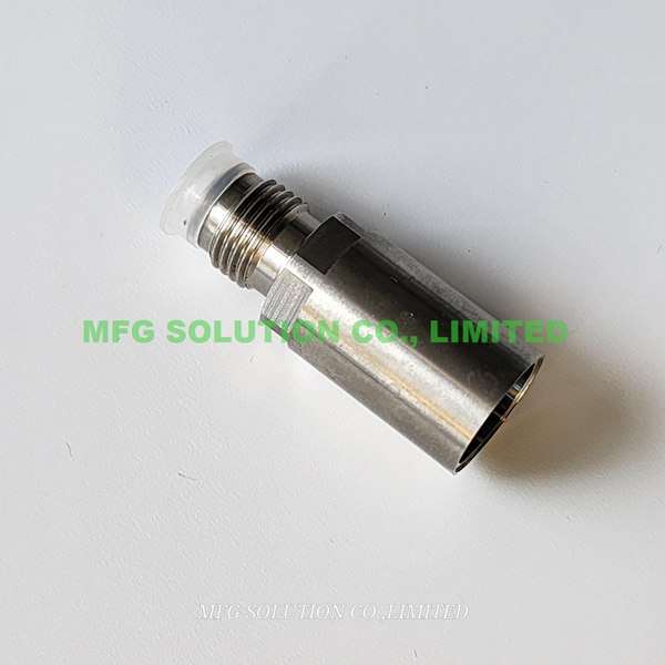
CNC threading optimization means selecting the right threading method, tooling, and machine parameters to maximize thread quality, extend tool life, and cut cycle times. Applying CNC threading optimization principles to your production process can reduce cycle time by 20–40% and nearly eliminate scrap from tolerance drift or tool breakage. The three core levers are method selection (thread turning, milling, or tapping), insert geometry matched to pitch and material, and machine rigidity settings that prevent chatter. According to SME’s threading strategies guidance, matching insert geometry to pitch and workpiece material is the single most impactful variable in threading performance.
What You’ll Need for CNC Threading Optimization
Successful CNC threading optimization starts with three prerequisites: a rigid, thermally stable machine, low-runout toolholding, and calibrated gauging for first-article verification.
Spindle Rigidity and Thermal Stability Requirements
Spindle runout must measure below 0.001″ at the spindle nose before you attempt any threading operation. Beyond that threshold, thread form accuracy degrades, particularly on fine-pitch threads below 32 TPI, where the insert tip traces a slightly elliptical path instead of a true helix.
Thermal stability is equally non-negotiable. A 10°F ambient temperature swing can shift thread pitch diameter by 0.0002″ on aluminum parts, enough to push a tolerance-critical thread out of class. Warm spindles up for 15–20 minutes before precision threading runs to let the machine reach thermal equilibrium and stabilize bearing clearances.
Toolholder and Workholding Setup Practices
Hydraulic or shrink-fit toolholders reduce radial runout to under 0.0001″, compared to 0.0005″ typical of collet chucks. That difference matters most in thread milling and small-diameter tapping, where even minor runout produces a bell-mouthed thread entry or inconsistent flank contact.
Workholding must fixture parts to less than 0.0005″ total indicated runout (TIR). Any movement beyond that introduces pitch-diameter variation across the thread length. For a detailed look at fixture selection and clamping strategy, see our guide on CNC Workholding Techniques & Fixtures Explained.
Finally, stock your inspection bench with GO/NO-GO thread ring and plug gauges, pitch micrometers, and an optical comparator. These three tools cover first-article verification across thread form, pitch diameter, and lead angle — the minimum metrology kit any shop needs before releasing a threaded part to production.
The essential equipment checklist for CNC threading optimization setup includes:
- GO/NO-GO thread ring and plug gauges for pass/fail verification
- Pitch micrometers for pitch diameter measurement
- Optical comparator for thread form and lead angle inspection
- Hydraulic or shrink-fit toolholders (runout under 0.0001″)
- Dial test indicator for TIR measurement at the workholding fixture
- Spindle warm-up timer (minimum 15–20 minutes before precision runs)
CNC Threading Optimization: Choosing the Right Method for Your Part
Picking the correct threading method before you cut your first chip is the single biggest lever in CNC threading optimization — wrong choice means scrapped parts or broken tools. As noted in Protolabs’ guide to threading considerations for CNC machining, thread milling is often the preferred approach for hard materials and large-diameter features where tap breakage risk is unacceptable.
“Selecting the wrong threading method for a given material is the most common and most costly mistake we see in production threading. The decision tree is simple — material hardness, hole geometry, and required tolerance class should drive method selection every time, not habit or familiarity.” — Dr. John Ziegert, Professor of Mechanical Engineering, University of Florida Department of Mechanical & Aerospace Engineering
Thread Turning vs. Thread Milling vs. Tapping: Speed and Accuracy Compared
Each method makes a different trade-off between cycle time, tolerance, and risk. The table below puts the three side by side on the metrics that matter most in production.
| Method | Cycle Time | Pitch Diameter Tolerance | Best Material Range | Primary Risk |
|---|---|---|---|---|
| Thread Turning | 3–8 sec per thread (1/2-13 UNC in steel) | ±0.001″–±0.002″ | All machinable metals, concentric features only | Limited to lathe-compatible geometry |
| Thread Milling | Slowest of the three | ±0.0005″ achievable | Exotic alloys, hard materials, large diameters | Longer cycle time; higher tooling cost |
| Tapping | Under 1 sec (1/4-20 in aluminum at 3,000 RPM) | Standard, pitch controlled by tap geometry | Aluminum and mild steel (<35 HRC) | Catastrophic breakage in hard materials (>40 HRC) |
Thread turning delivers the fastest cycle time for external threads on turned parts — 3 to 8 seconds per thread on a 1/2-13 UNC in steel — making it the default for high-volume lathe work. The constraint is geometry: it only works on concentric, lathe-accessible features.
Tapping wins on throughput for internal threads in soft materials. A rigid tap in aluminum at 3,000 RPM completes a 1/4-20 hole in under one second. But push that same tap into material above 40 HRC and breakage risk becomes a production-stopping event, not a minor inconvenience.
Thread milling is the slowest option, but it achieves pitch diameter tolerances of ±0.0005″ — tighter than either alternative. It also eliminates tap breakage risk entirely, which matters most when machining titanium, Inconel, or hardened stainless.
When to Choose One Threading Method Over Another
Apply this decision rule before programming any threaded feature. Use the following criteria to guide method selection:
- Thread milling: Any thread in material above 35 HRC; any thread larger than 1.5″ diameter; any blind hole where extracting a broken tap would require scrapping the part; titanium, Inconel, or hardened stainless applications
- Tapping: Maximum throughput on standard pitches in aluminum or mild steel; confirmed rigid tapping with synchronized spindle control; through-holes or shallow blind holes in materials under 35 HRC
- Thread turning: Part already runs on a CNC lathe; thread is external and concentric; high-volume production where 3–8 second cycle times are acceptable
At MFG SOLUTION, our 60+ engineering professionals evaluate material hardness, hole depth, and diameter against these criteria before selecting a method — so your threading process is determined by part requirements, not habit.
Select the Correct Cutting Tools and Inserts for Each Thread and Material
Match your insert geometry and coating to thread pitch and workpiece material — that single decision drives tool life, thread accuracy, and scrap rate more than any other CNC threading optimization variable. According to ASME’s thread standards and tolerances reference, using the correct coating for the workpiece material can extend insert life by 3–5× compared to uncoated carbide in steel applications.
“Insert coating selection is not a secondary consideration — it is a primary driver of tool life and thread surface finish. In our testing, TiAlN-coated inserts in stainless steel threading applications consistently outperformed TiN coatings by a factor of three or more in edge life before dimensional drift.” — Dr. Radu Pavel, Director of Research, TechSolve Manufacturing Research Institute
Tool Geometries and Coatings for Fine vs. Coarse Pitch Threads
Fine-pitch threads above 32 TPI require full-profile inserts with sharp cutting edges. A TiN or TiAlN coating protects the edge without adding the radius that causes crest rollover — a defect that partial-profile inserts produce on fine pitches and that directly raises scrap rate. If you’re using partial-profile inserts on anything above 32 TPI, expect dimensional rejects.
Coarse-pitch threads below 16 TPI generate significantly higher chip loads. Use indexable inserts with a 60° included angle and an AlTiN coating. In steel, that combination delivers 3–5× longer tool life compared to uncoated carbide — a measurable cost reduction on high-volume runs.
How Material Properties Drive Insert Selection
Aluminum alloys — 6061 and 7075 specifically — build up on the cutting edge quickly. Use uncoated or ZrN-coated carbide with a high positive rake angle of 15–20°. Run thread turning at 400–600 SFM to prevent built-up edge without sacrificing cycle time.
Stainless steel (304, 316) and titanium demand TiAlN-coated inserts with chipbreaker geometry. Cut your SFM by 40% compared to carbon steel, and run flood coolant throughout. Coolant selection for these materials is a separate decision — see our CNC Coolants and Lubricants guide for a full breakdown.
Exotic alloys — Inconel, Hastelloy — sit above 45 HRC and will fracture standard carbide inserts under thread turning loads. CBN or ceramic inserts handle the hardness, but thread milling with solid carbide end mills is often the safer and more cost-effective approach. The lower radial forces in thread milling reduce the risk of catastrophic insert failure on a finished part.
Insert Grade Selection by Thread Standard
Thread standard also influences insert grade selection. Unified National (UN) threads cut in carbon steel are well served by PVD-coated carbide grades in the P25–P35 range, which balance toughness and wear resistance across a wide cutting speed window. Metric ISO threads in stainless steel benefit from a finer grain carbide substrate — grades in the M15–M25 range — because the tighter pitch demands a sharper edge that coarser substrates cannot maintain without micro-chipping.
Pipe threads (NPT, BSPT) present a unique challenge: the tapered form requires the insert to engage progressively deeper material as it advances. Use a full-profile insert rated for interrupted cuts, and reduce depth of cut by 15% compared to straight-thread applications to compensate for the increasing radial load. For reference on thread form standards and dimensional requirements, the NIST thread measurement monograph provides authoritative dimensional data for UN, metric, and pipe thread forms used in precision manufacturing.
Troubleshoot Common CNC Threading Problems
Most CNC threading failures trace back to three root causes: chatter, tool breakage, and tolerance drift — each with a specific, correctable fix.
What Causes Chatter in CNC Threading and How to Eliminate It
Chatter in thread turning is almost always caused by excessive tool overhang, insufficient spindle RPM, or worn spindle bearings. Keep tool overhang below 3× the insert height — beyond that threshold, the insert deflects under cutting load and produces the harmonic vibration you hear as chatter.
The fastest corrective action: reduce depth of cut by 20% and increase feed rate by 10%. That combination lowers cutting force while maintaining chip formation, and in most cases eliminates chatter without adding cycle time. If chatter persists after those adjustments, check bearing runout — a worn bearing introduces enough radial play to destabilize any threading pass.
Torn thread flanks are a separate surface finish problem. They indicate a dull insert or insufficient coolant rather than a setup issue. Built-up edge on the insert tip, common in aluminum, produces a rough finish; switch to a sharper rake angle and raise coolant pressure to a minimum of 500 PSI to flush chips away from the cutting zone before they re-cut the flank.
Why Threading Tools Break and How to Prevent Premature Failure
Taps break when chip load exceeds the tool’s tensile strength — a failure mode that accelerates in blind holes where chips have nowhere to go. Use spiral-flute taps for blind-hole applications; the flute geometry ejects chips upward and out of the hole rather than packing them at the bottom. Limit tap engagement to 1.5× diameter in steel, and program a 10% speed reduction over the last 20% of thread depth, where torque peaks.
Tolerance drift is a slower failure but equally costly. Thermal growth during long production runs shifts pitch diameter outside specification. A practical CNC threading optimization routine: run a tool offset compensation check every 50 parts and use in-process gauging to catch drift before it generates scrap. For a detailed breakdown of allowable deviations by thread class, see our internal guide on Machining Tolerances Explained.
The cost case for switching methods is real. A shop running 304 stainless thread milling cut scrap from 8% to under 1% by replacing tapping with thread milling and adding TiAlN-coated solid carbide mills. Cycle time increased 12 seconds per part, but scrap cost savings exceeded $18,000 per year — making the tradeoff straightforward.
At MFG SOLUTION, our 60+ engineering professionals apply in-process gauging and offset compensation routines as standard practice on stainless and medical-grade alloy runs, helping customers hold thread tolerances across batch production without manual inspection at every part.
Common Mistakes to Avoid in CNC Threading
Five setup and programming errors account for the majority of rejected threading operations — catching them early is the fastest CNC threading optimization win available.
“The most preventable threading failures we audit in production environments come down to two things: wrong starting-point synchronization in G-code and skipping coolant on work-hardening alloys. Both are zero-cost fixes that eliminate the majority of scrap in a threading cell.” — Mark Terryberry, Senior Applications Engineer, Modern Machine Shop
1. Wrong Thread Starting Point in G-Code
Failing to synchronize the spindle encoder with the threading pass start produces drunken threads — each pass cuts a slightly different helix. Always command a consistent spindle orientation with M19 before the first threading pass. This locks the encoder reference so every subsequent pass tracks the same angular start point.
2. Ignoring Material Hardness When Choosing Tap vs. Mill
Tapping any material above 35 HRC without a rigid tapping cycle and a spiral-flute tap is a predictable failure. Shops routinely spend more time extracting broken taps than they saved on cycle time. Use thread milling above that hardness threshold — it gives you climb-milling control and a recoverable tool path if something goes wrong.
3. Skipping Coolant on Stainless and Titanium
Dry threading in austenitic stainless work-hardens the surface between passes, accelerating insert wear by up to 3×. Flood coolant or high-pressure through-tool coolant is non-negotiable on these materials. MFG SOLUTION applies through-tool coolant as standard on all stainless and titanium threading operations to protect insert life and hold tolerance across full production runs.
4. Using Partial-Profile Inserts on Fine-Pitch Threads
Partial-profile inserts leave an unfinished crest that fails GO gauge inspection. Full-profile inserts cost 15–20% more per unit but eliminate a secondary deburring or re-threading operation that costs far more in labor and throughput. The math favors the better insert every time on fine-pitch work.
5. Overlooking Tolerance Stackup on Multi-Start Threads
Each start on a multi-start thread compounds positional error — a mistake that only surfaces at final inspection, after full machining cost is sunk. For the calculation method, see our internal guide on Precision Tolerance Stackup. Audit your G-code offsets for each start before cutting the first part.
Frequently Asked Questions
How much can CNC threading optimization actually reduce cycle time?
Optimized threading parameters can cut cycle time by 20–40% on high-volume runs, depending on material, thread type, and toolpath strategy. The largest gains typically come from switching to single-point thread turning with constant chip load, eliminating redundant spring passes, and matching feed rate precisely to thread pitch. On parts with multiple threaded features — common in automotive connectors and medical housings — those savings compound across every cycle in a batch run.
What spindle speed and feed rate should I use for threading stainless steel?
For stainless steel threading, start with a surface cutting speed of 80–120 SFM and set feed rate equal to the thread pitch per revolution. Stainless work-hardens quickly, so dwelling in the cut causes built-up edge and premature insert wear. Use a sharp, positive-rake insert geometry, apply high-pressure coolant directed at the cutting zone, and avoid any feed rate deviation — even small inconsistencies produce pitch errors that fail gauge inspection.
Is thread milling accurate enough to replace tapping for precision medical device components?
Thread milling matches or exceeds tapping accuracy for medical components, routinely holding tolerances to 4H/4G class fits on internal threads. It also eliminates tap breakage risk inside expensive titanium or stainless blanks — a critical advantage when a broken tap means scrapping a part worth hundreds of dollars. MFG SOLUTION’s ISO 13485:2016-certified process uses thread milling for tight-tolerance medical parts precisely because it gives full control over thread form, depth, and fit class without the catastrophic failure mode tapping carries.
How do I know when a threading insert needs to be replaced before it causes scrap?
Replace a threading insert when surface finish degrades, cutting forces rise noticeably, or you see chipping on the insert’s flank face during visual inspection between cycles. Don’t wait for a failed part to trigger the change. Set a conservative tool-life limit in your CNC program — tracked by part count or cutting time — and audit the first thread on each new insert with a thread gauge to confirm the changeover point is calibrated correctly for your material and speed.
What are the key parameters to document when establishing a repeatable CNC threading optimization process?
A repeatable CNC threading optimization process requires documenting spindle speed (SFM), feed rate (IPR matched to pitch), depth-of-cut per pass, number of passes, insert grade and coating, coolant pressure, tool overhang length, and offset compensation interval (parts between checks). Record first-article gauge results alongside these parameters for every new job setup. This baseline allows rapid troubleshooting when drift occurs and enables consistent replication across shifts, operators, and machine restarts without re-qualifying from scratch.
Conclusion
CNC threading optimization comes down to three decisions made before the spindle turns: choosing the right threading method for your part geometry and material, dialing in speed and feed to match thread pitch exactly, and building tool-life limits into your program before scrap forces the issue. Get those three right and cycle time, surface quality, and first-pass yield all improve together. For further reference on threading design considerations, review the NIST thread measurement standards and SME’s threading application resources as authoritative starting points for process development.
If your threading operations involve small precision parts under 38mm — particularly for medical, automotive, or electronics applications — submit your specifications to MFG SOLUTION. You’ll receive a detailed quote within 8 hours, backed by ISO 9001:2015, ISO 13485:2016, and IATF 16949 certification. Start there: upload your thread specs and request a process recommendation alongside the quote.
Recommended Articles
Explore more from our content library: