
2026-11-06
How to Reduce Machining Time Without Risking Part Quality

Understanding how to reduce machining time is essential. You reduce CNC machining time by cutting non-productive time (setups, tool changes, repositioning) and optimizing cutting parameters (speeds, feeds, toolpaths) at the same time, not by pushing feeds and speeds alone, which risks tool wear, chatter, and scrapped tolerances. The biggest gains usually come from fewer setups, standardized tooling, and part designs that avoid unnecessary tight tolerances or complex geometry, combined with cutting data matched to the material and tool. Quality holds when changes are tested and verified in small steps rather than applied all at once.
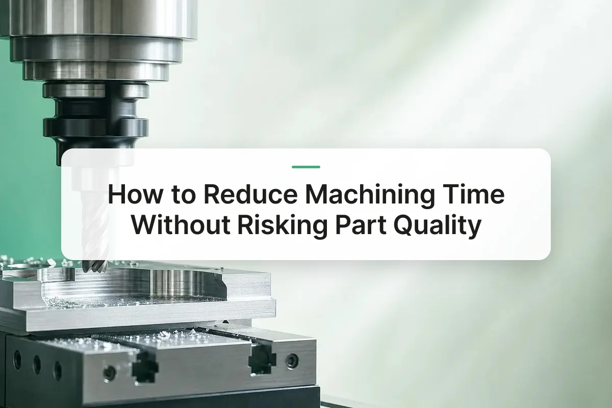
Identify What’s Actually Slowing Down Your CNC Cycle Time
Before changing feeds, speeds, or fixturing, break down where time actually goes on each operation, guessing leads to fixing the wrong bottleneck. Any real plan for how to reduce machining time starts with a measurement, not an assumption.
Cycle Time vs. Setup Time vs. Total Lead Time
Cycle time, setup time, and total lead time measure three different things, and treating them as one number is the most common diagnostic mistake shops make. Cycle time is the spindle-on machining per part. Setup time covers fixturing, tool loading, and program zeroing before the spindle ever turns. Total lead time wraps in queueing, inspection, material staging, and shipping prep. A shop that shaves 10 seconds off cycle time on a high-mix, low-volume job while ignoring a two-hour changeover has optimized the wrong variable. Tracking all three separately, even with a simple spreadsheet per job, shows whether your real cost driver is machine time, changeover frequency, or scheduling delays upstream of the machine.
How Tool Wear Affects Machining Time Across a Production Run
Tool wear doesn’t just degrade one part, it slows every part after it, because dulling edges force lighter cuts, extra passes, and more frequent retouches as the run progresses. A fresh insert might clear a pocket in two passes; the same insert at 70% of its life may need three or four to hold the same tolerance. Left unmanaged, tool wear also drives thermal drift: extended cycle times generate more heat in the workpiece, and that heat causes dimensional shifts that push parts toward the edge of tolerance. Tracking tool life by cut count or spindle hours, not by visual inspection alone, catches this before it compounds across a batch.
Non-cutting time deserves equal scrutiny. Tool changes, rapid repositioning between features, air-cutting over empty stock, and manual inspection stops between operations can consume as much time as the actual cutting. None of these show up if you only track total cycle time, they hide inside it.
Tolerances and geometry compound all of this. Specifying a tolerance tighter than the function requires, or designing a deep pocket with thin walls, forces slower feeds, more finishing passes, and more frequent operator checks to confirm the part hasn’t drifted. A time breakdown per operation, cutting, tool change, inspection, idle, is the prerequisite that tells you which of these factors is actually costing you the most, before you touch a single parameter.
How to Reduce Machining Time by Optimizing Speeds and Feeds
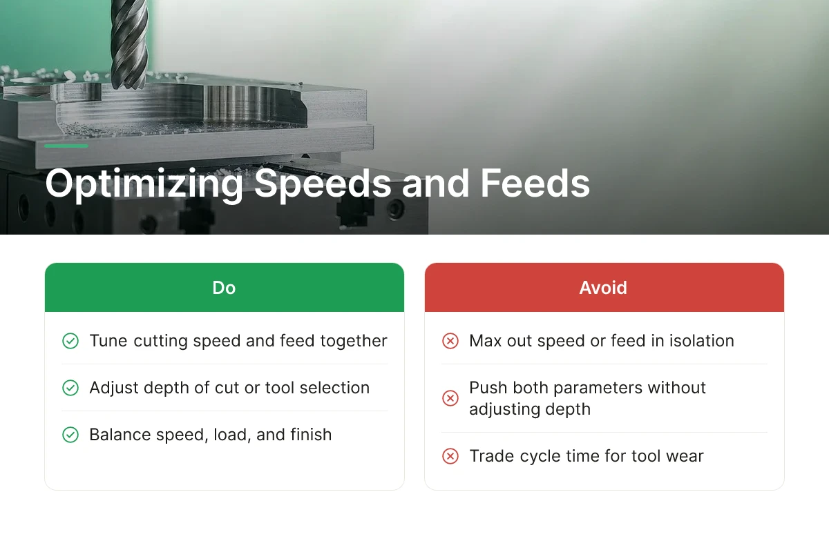
The fastest route to lower cycle times is tuning cutting speed and feed rate together rather than maxing out either one in isolation. Push speed too far and you trade cycle time savings for tool wear, scrap, and rework, a net loss on any precision job.
Cutting speed, feed rate, tool life, and surface finish move as a connected system, not four independent dials. Raise the spindle speed and you generate more heat at the cutting edge; raise the feed rate and you increase load per tooth. Push both at once without adjusting depth of cut or tool selection, and surface finish degrades before you notice the tool is failing. The goal when figuring out how to reduce machining time is finding the combination that holds tolerance and finish at the lowest safe cycle time, not the combination that runs fastest on paper.
What Happens When Cutting Speed Is Too High
Excess cutting speed shows up first as accelerated tool wear, then as heat buildup, chatter, and dimensional drift on the finished part. Heat generated during an overly aggressive cut transfers into the workpiece, and thermal expansion shifts dimensions out of tolerance even when the program itself is correct. Chatter, vibration from an unstable cut, leaves visible marks on the surface finish and accelerates edge breakdown on the insert. The fix is incremental: back off spindle speed or feed in small steps, re-cut a test piece, and check for vibration, sound, and chip color before moving forward. A stable cut sounds consistent and produces uniform chips; a cut running too hot or too fast sounds erratic and often produces discolored, blue-tinted chips on steel.
How HSM and Adaptive Feed Strategies Cut Cycle Time on Precision Parts
High-speed machining (HSM) reduces cycle time by taking lighter, faster cuts along optimized toolpaths instead of removing more material per pass. The tool stays engaged at a consistent, shallow depth, which keeps cutting forces predictable and reduces the heat spikes that come from heavier conventional cuts. Adaptive clearing strategies work alongside HSM by adjusting feed rate in real time based on how much material the tool is actually engaging, slowing down in corners and heavy engagement zones, speeding up in open pockets where chip load is light. This removes the wasted motion of a single fixed feed rate run across geometry that varies constantly.
Test changes incrementally: adjust one parameter, run a verification part, measure it against the print, then commit to the full batch. MFG SOLUTION builds this parameter validation into production planning across its CNC turning, Swiss lathe, and CNC mill & turn processes, so speed and feed settings are proven on parts up to 38mm in diameter before a job scales to volume.
Choose Designs and Materials That Machine Faster
Part geometry and material choice set the ceiling on machining speed before a part ever reaches the spindle, this is where the answer to how to reduce machining time usually starts. Correcting these decisions upstream prevents slow, conservative cutting from becoming the only option later.
How Material Selection and Part Geometry Affect Machining Speed
Material hardness and machinability rating determine the spindle speeds, feed rates, and depth of cut a shop can safely run. Free-machining aluminum alloys and leaded brass form short, manageable chips and tolerate aggressive feeds; hardened steels and titanium generate heat fast, wear tools quickly, and force slower, lighter passes to avoid chatter and tool failure. Chip formation matters as much as hardness, a material that curls into clean chips keeps cutting continuous, while one that produces long stringy chips requires pauses to clear the tool path, adding non-cutting time to every cycle.
Part geometry compounds these material limits. Deep pockets require long tool stickout, which reduces rigidity and forces slower feeds to avoid deflection. Thin walls flex under cutting pressure, so the only way to hold dimension is to take lighter cuts in more passes. Sharp internal corners can’t be reached by a single tool radius, often requiring a tool change or a slower finishing pass just to clean up a feature with no functional purpose. Each of these geometry choices adds cycle time independent of the machine’s capability.
Why Looser Tolerances and Simpler Designs Cut Machining Time
Tolerances tighter than the application needs add cost in two places: slower, more conservative cutting passes to hold the dimension, and longer inspection cycles to verify it. A tolerance of ±0.01mm on a feature that only needs ±0.05mm forces the shop to run reduced feed rates and add in-process measurement steps that a looser spec would skip entirely.
Standard hole sizes that match common drill diameters, generous corner radii that match standard tool geometry, and consistent wall thickness throughout a part all reduce the number of tool changes and the amount of conservative machining a job requires. These are not downgrades, they’re design choices that match the part to how cutting tools actually move.
Simplifying a design is a conversation, not a unilateral edit. At MFG SOLUTION, engineers review incoming specifications against the five manufacturing methods available, CNC turning, Swiss lathe, cold forging, automatic lathe, and CNC mill & turn, and flag where a tolerance, radius, or wall thickness can be relaxed without affecting fit or function, before quoting within 8 hours. That collaboration between engineering and the shop floor is where geometry and material choices turn into real cycle-time savings.
Reduce Setup Time and the Number of Setups Per Job
Cutting the number of setups per job is one of the most reliable answers to how to reduce machining time on short-run precision parts, because non-cutting time, loading, aligning, re-zeroing, often exceeds actual spindle time on small-batch work.
Every time a part comes off the machine and gets re-fixtured, it reintroduces alignment risk. The operator has to re-establish datums, re-zero axes, and re-verify the part sits exactly where the program expects it. Even with a skilled crew, each re-clamp adds variation that can push critical features out of tolerance. A part machined complete in one setup skips that risk entirely and eliminates the dead time between operations, no waiting for a second machine, no queue for a secondary process.
Standardizing Part Features and Tooling Across Jobs
Reusing the same hole sizes, thread types, and fillet radii across a product line lets a shop reuse tooling, offsets, and programs instead of building them from scratch each time.
- Specify standard drill and tap sizes wherever the design allows, rather than custom diameters that force a one-off tool purchase or substitution.
- Keep fillet radii consistent with standard end-mill or insert radii already in the shop’s tool crib, so a cutter change isn’t required mid-job.
- Group similar parts into families with shared setups, so fixture offsets and work coordinate systems carry over from one job to the next with minimal re-entry.
This kind of standardization is also what lets a job shop quote fast. At MFG SOLUTION, consistent tooling libraries and pre-validated offsets across CNC turning, Swiss lathe, and mill-turn processes support quotes within 8 hours, because engineers aren’t re-deriving a process from zero for every new part.
Designing Parts to Minimize Secondary Operations and Re-Fixturing
Orienting features so they’re all accessible from one setup removes the need for re-clamping, manual deburring, or a second machine pass.
Design for Manufacturability principles push engineers to review part orientation before it ever reaches the shop floor. If a feature can be moved to the same face as the rest of the geometry, or reached with a different tool angle instead of a flip, the part can run complete in one clamping. That change alone removes an entire category of non-cutting time: unclamping, flipping, re-indicating, and re-zeroing.
Workholding standardization compounds the effect across an entire production schedule. Modular fixtures and pallet systems let a shop swap jobs without rebuilding a fixture from scratch, cutting changeover time between unrelated orders. For shops with 5-axis CNC or mill-turn equipment, MFG SOLUTION runs 5-axis machines alongside 20 automatic lathes, multiple operations that once required separate setups can run in a single cycle, trading equipment capability for time saved on handling and alignment.
Avoid These Common Mistakes When Trying to Machine Faster
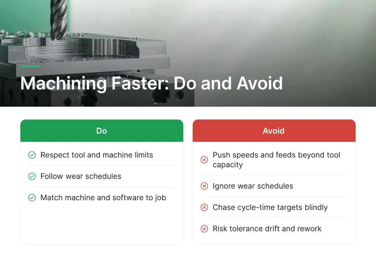
Most failed attempts at how to reduce machining time come from the same handful of errors: pushing parameters past tool limits, ignoring wear schedules, and running the wrong machine or software for the job. Each mistake erases the gains it was supposed to create, often at the cost of scrap parts or unplanned downtime.
The first mistake is chasing a cycle-time target by increasing speeds and feeds beyond what the tool and machine can actually sustain. A 10% cut in cycle time means nothing if it produces a tolerance drift or a finish that fails inspection and sends the part back for rework. Cutting parameters need to respect the tool manufacturer’s limits and the machine’s rigidity, not a spreadsheet goal set without shop-floor input.
The second mistake is treating tool wear as an afterthought. Shops that run tools past their effective life see inconsistent cycle times from part to part, then lose hours mid-run when a worn edge finally fails. Thermal expansion from extended cycles can also shift dimensions mid-batch, which is why tool condition and cycle time should be tracked together rather than separately.
Choosing Between CNC Machines and CAM Software for Speed
CAM software without adaptive toolpath generation or cutting simulation caps cycle-time gains regardless of how capable the machine is. Adaptive toolpaths adjust the cut to maintain constant tool engagement, which lets the spindle run faster without overloading the cutter, a feature older or mismatched CAM packages often lack.
Machine selection matters just as much as the programming. A part with multiple features on different faces machined on a 3-axis mill with several setups will always take longer than the same part run complete on a 5-axis or mill-turn platform. The decision should follow part complexity, not default to whatever is already sitting on the floor. MFG SOLUTION applies this logic directly: with 5-axis CNC machines, Swiss lathes, and 20 automatic lathes available, each job gets matched to the method that minimizes setups and machining time rather than forced onto a single default process.
Managing Tool Wear and Tool Changes to Avoid Downtime
Tool change scheduling built around actual tool life data, not guesswork, prevents the mid-run surprises that erase any time saved upstream. Tracking cutting hours per tool and replacing inserts on a planned schedule keeps cycle times consistent across a batch instead of degrading as edges dull.
Combined, these checks form a simple troubleshooting sequence: verify parameters against tool and machine limits, confirm CAM software supports adaptive cutting, match the machine to part complexity, and schedule tool changes proactively. Skipping any one step tends to reintroduce the downtime or quality risk that efforts to reduce machining time were meant to eliminate in the first place.
Frequently Asked Questions
Does reducing machining time always mean lowering part quality?
No, cutting machining time and maintaining quality are not in conflict when the reduction comes from eliminating waste, not cutting corners. Faster cycles achieved through optimized toolpaths, correct speeds and feeds, or simplified geometry often improve consistency because the part spends less time generating heat and drifting out of tolerance. Problems only arise when speed is pushed past what the tool, material, or fixture can handle.
How much of total lead time is actually spent cutting versus setting up?
Setup, fixturing, and tool changes frequently consume more time than actual cutting on small, complex parts. Every added feature or re-fixturing step compounds non-cutting time, which is why reducing setup count often saves more than tweaking spindle speed alone.
Can software alone reduce machining time without changing the part design?
Software helps, but it has limits if the design itself fights the process. CAM toolpath optimization and simulation can cut unnecessary air-cutting moves and improve feed consistency, but a part with deep pockets, thin walls, or sharp internal corners will still run slow no matter how well the program is written.
When should you involve a machine shop in design decisions to reduce machining time?
Bring in the machine shop during initial CAD review, before drawings are finalized for quoting. Early design-for-manufacturability input catches tolerance and geometry issues that are cheap to fix on screen but expensive to rework after tooling and fixtures are built.
Conclusion
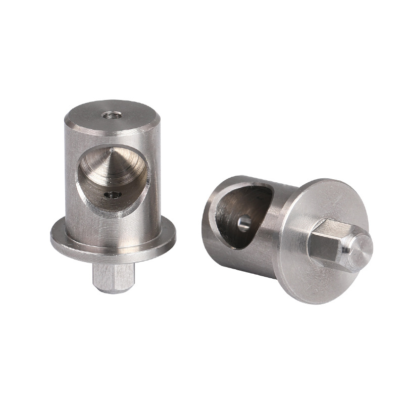
Cutting machining time comes down to three decisions: simplify part geometry before it reaches the shop floor, apply tight tolerances only where function demands them, and match the manufacturing method, CNC turning, Swiss lathe, cold forging, or mill-turn, to the part instead of forcing one process to do everything. Each choice compounds; a design review that removes two unnecessary features can save more cycle time than any spindle speed adjustment. If you’re sourcing parts under 38mm, start by sending your CAD file to MFG SOLUTION for a quote within 8 hours, the response will flag geometry or tolerance choices that are adding machining time before you commit to tooling.
Recommended Articles
Explore more from our content library: