
2026-07-21
Guide to the Forging Procedure: Steps and Methods

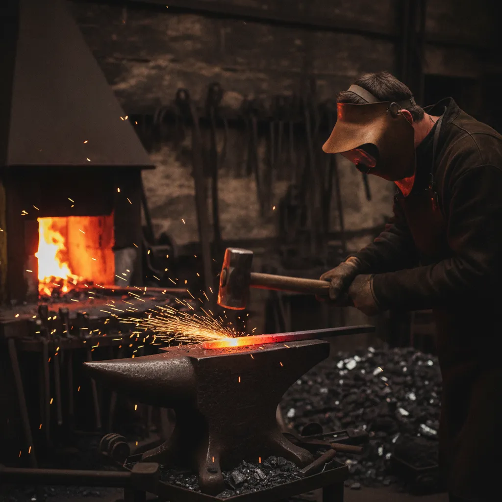
The forging procedure is a metalworking process that shapes metal using compressive forces, typically applied through hammers, presses, or dies, to produce parts with superior grain structure and mechanical strength compared to casting or machining from bar stock. Metal is heated to a workable temperature (or worked cold), then deformed into a die or under a hammer to achieve the target geometry. The result is a denser, stronger part with fewer internal voids, which is why forged components dominate safety-critical applications in aerospace, automotive, and medical manufacturing. According to Wikipedia’s overview of forging, the process dates back thousands of years and remains one of the most reliable methods for producing high-strength metal components.
The Forging Procedure Step by Step
A complete forging procedure runs from alloy selection and billet cutting through heat treatment and dimensional inspection, typically six to eight discrete steps depending on part complexity. According to Ferralloy Inc’s breakdown of the forging process, each stage must be carefully controlled to ensure the final part meets mechanical and dimensional specifications.
“The forging procedure is only as strong as its weakest step — poor billet preparation or inadequate die lubrication will undermine even the best press setup.” — Dr. Taylan Altan, Professor Emeritus, Center for Precision Forming, The Ohio State University
The key stages of a standard forging procedure include:
- Material selection and billet preparation — Engineers select the alloy (carbon steel, aluminum, or titanium) based on mechanical requirements, then cut billets to a precise weight tolerance.
- Heating — Carbon steel billets for hot forging are heated to 2,100–2,300°F in a medium-frequency furnace. Borax flux is applied to prevent oxidation.
- Die setup and lubrication — Dies are aligned to tight positional tolerances; graphite-based lubricants are standard for hot forging, zinc stearate for cold forging.
- Forging stroke — A hammer or hydraulic press applies compressive force to fill the die cavity, often requiring multiple blows with repositioning between each.
- Trimming — Flash is removed in a dedicated trimming press matched to the forging die geometry.
- Heat treatment — Parts are normalized, annealed, or quenched and tempered to achieve target hardness and grain structure.
- Inspection and documentation — Dimensional, surface, and internal integrity checks confirm the part meets drawing tolerances.
Step 1: Material selection and billet preparation. Engineers select the alloy, carbon steel, aluminum, or titanium, based on the part’s mechanical requirements, then cut billets to a precise weight tolerance. Tight weight control here reduces excess flash and minimizes material waste downstream.
Step 2: Heating. Carbon steel billets for hot forging are heated to 2,100–2,300°F in a medium-frequency furnace. During open-die heating, borax flux is applied to the billet surface as a scale inhibitor, it prevents oxidation that would otherwise pit the die face and degrade surface finish on the finished part.
Step 3: Die setup and lubrication. Dies are aligned to tight positional tolerances before the first stroke. Graphite-based lubricants are standard for hot forging; zinc stearate is used in cold forging operations. Lubricant choice directly affects both die life and part surface finish, inadequate lubrication accelerates die wear and increases rejection rates.
Step 4: Forging stroke. A hammer or hydraulic press applies compressive force to fill the die cavity. Impression die forging typically requires multiple blows with repositioning between each, because a single stroke rarely achieves full cavity fill without cracking the billet.
What Happens in the Final Step of the Forging Process
The final steps cover trimming, heat treatment, and inspection, the stage where a rough forging becomes a dimensionally verified part. Understanding what occurs at the end of the forging procedure is critical for ensuring part quality and traceability.
Step 5: Trimming. Flash, the thin metal fin that squeezes out between die halves, is removed in a dedicated trimming press. Trimming dies are matched to the forging die geometry to cut cleanly without distorting the part.
Heat treatment follows trimming. Depending on the alloy and application, parts are normalized, annealed, or quenched and tempered to achieve the target hardness and grain structure. For automotive and medical components, this step is documented and traceable to the specific heat lot.
Quality Control and Inspection Standards During Forging
Dimensional inspection against drawing tolerances is the checkpoint that separates a usable forging from scrap. Parts are checked for critical dimensions, surface condition, and, on structural components, internal integrity via ultrasonic or magnetic particle testing.
For manufacturers sourcing small precision forged parts, this inspection stage connects directly to tolerance stackup requirements at the assembly level. MFG SOLUTION’s cold forging operations, certified to ISO 9001:2015 and IATF 16949, apply full process control at each step, every stage tracked, documented, and auditable, for parts up to 38mm in diameter destined for automotive and electronics assemblies.
Hot, Warm, and Cold Forging: How the Methods Compare
The forging procedure you choose determines dimensional tolerance, surface finish, part strength, and total production cost more than any other single variable. Each method follows a distinct forging procedure suited to different materials, geometries, and production volumes.
“Selecting the correct temperature range is the single most consequential decision in any forging procedure — it governs metal flow, die life, and the final mechanical properties of the part.” — Sanjay Tambe, Senior Metallurgical Engineer, Forging Industry Association
Hot forging heats steel above its recrystallization temperature, typically 1,800–2,300°F, which reduces forming forces and allows complex shapes and large cross-sections to be produced. The tradeoff is dimensional accuracy: hot-forged parts typically hold tolerances of ±0.030 in., and oxide scale on the surface usually requires secondary machining or shot blasting to clean up.
Warm forging operates between 400–1,800°F for steel. It reduces the press tonnage needed compared to cold forging while still delivering tighter dimensions than hot forging, a practical choice for medium-complexity parts where cold forging forces would exceed equipment capacity.
Cold forging works at room temperature. The process achieves tolerances of ±0.005 in. or better, produces a cleaner surface finish, and introduces strain hardening that raises tensile strength. Cold-forged parts show 10–20% higher yield strength than hot-forged equivalents because plastic deformation at low temperature compresses the grain structure rather than allowing it to recrystallize. This makes cold forging the preferred method for high-volume fasteners, pins, and shafts, particularly parts up to 38mm diameter, where MFG SOLUTION’s cold heading equipment is optimized for batch production.
Hot-forged parts retain better ductility, which simplifies post-forge CNC turning or milling operations where material removal is extensive.
The table below summarizes the key differences between the three forging procedure types:
- Hot forging: Temperature 1,800–2,300°F; tolerance ±0.030 in.; best for large, complex shapes; requires post-forge surface treatment.
- Warm forging: Temperature 400–1,800°F; intermediate tolerance; balances forming force and dimensional accuracy.
- Cold forging: Room temperature; tolerance ±0.005 in. or better; highest surface finish; introduces strain hardening for increased strength.
Cost and Efficiency Differences Between Impression Die Forging and Open Die Forging
Cold forging carries higher upfront tooling costs, precision dies must withstand full room-temperature forming loads, but per-part cost drops sharply at volume because secondary machining is minimal. Hot forging uses less expensive dies and lower press tonnage, but energy consumption during heating and the cost of post-forge machining and surface treatment add back into the total unit cost. Impression die forging has a high initial cost due to engineering, designing, and manufacturing dies, yet those dies are reusable across long production runs, making the process cost-effective at scale. Open die forging requires less tooling investment and suits large, simple geometries, but it cannot match the dimensional repeatability that closed-die or cold forging delivers for precision components. For a detailed comparison of these approaches, Rex Forge’s forging process overview provides useful industry context.
Equipment and Tooling Used in Forging Operations
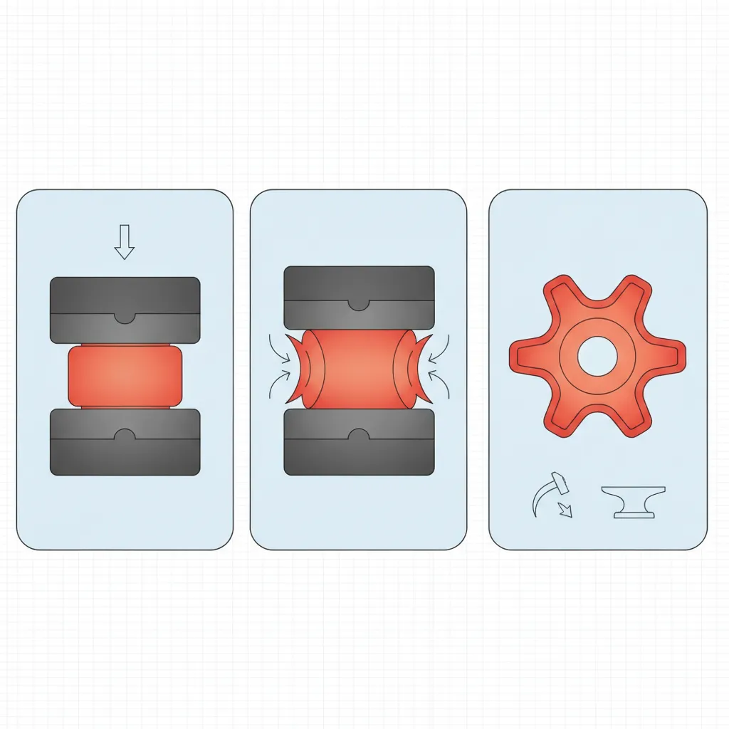
Forging operations rely on four main machine types—drop hammers, mechanical presses, hydraulic presses, and screw presses—each suited to different part sizes, volumes, and materials. The equipment selected must match the specific forging procedure being performed to ensure consistent results.
Drop Hammers
Gravity and power-assisted drop hammers deliver impact energy ranging from 50,000 to 500,000 ft-lbs for large industrial applications. That rapid, repeated impact makes them the practical choice for open-die work and small impression-die forgings where flash control is less critical than speed.
Mechanical Presses
Mechanical presses are rated by tonnage—typically 500 to 8,000 tons—and operate with a fixed stroke length that produces consistent part geometry across high-volume runs. Cycle times under 10 seconds make them the volume sweet spot for automotive-scale impression die forging, where per-part cost drops sharply with quantity.
Hydraulic Presses
Hydraulic presses reach up to 50,000 tons of force and allow variable stroke speed throughout the forging procedure. That controllability makes them the only practical option for large aerospace titanium forgings and multi-step operations where metal flow must be managed precisely. Capital cost runs $500,000 to $5M+, but per-part cost on large, complex components is the lowest of any press type.
Die Materials and Cost
H13 tool steel dies for hot forging cost $5,000 to $50,000+ depending on part complexity. Cold forging dies in carbide or D2 steel carry a higher upfront cost but last roughly 10 times longer at production volume—making them the more economical choice for high-run cold heading operations, the same process MFG SOLUTION applies using dedicated cold heading equipment for small precision parts up to 38mm in diameter.
Where Forged Parts Are Used: Aerospace, Automotive, and Medical Applications
Forged parts appear in aerospace, automotive, medical, and oil and gas applications because the forging procedure produces grain flow, strength, and fatigue resistance that casting cannot match. Each industry relies on a tailored forging procedure to meet its specific performance and compliance requirements.
In aerospace, titanium and nickel-alloy forgings are specified for turbine discs, landing gear assemblies, and structural bulkheads. Wrought grain flow aligned to the part geometry increases fatigue life by up to 30% compared to machined billet. Parts must meet AMS 2750 pyrometry standards for heat treatment temperature uniformity and pass NADCAP audits before they enter flight-critical assemblies.
Automotive applications rely on impression die forging in 4140 or 4340 steel for connecting rods, crankshafts, steering knuckles, and CV joints. A typical passenger vehicle contains more than 250 forged components, each selected because the process produces consistent, auditable mechanical properties at high production volumes.
Medical device manufacturers specify Ti-6Al-4V or Co-Cr alloys for orthopedic implants including hip stems and bone plates. Forging eliminates the shrinkage porosity that causes implants to fail fatigue testing under ISO 5832 biocompatibility standards. For manufacturers producing these components at tight tolerances, post-forge CNC machining of medical devices is the standard finishing path, a capability MFG SOLUTION supports under its ISO 13485:2016 certification.
Oil and gas valve bodies and flanges are forged to ASTM A105 or ASTM A182 specifications, achieving pressure ratings up to 15,000 PSI. Casting cannot reliably meet those ratings because shrinkage voids reduce burst strength unpredictably.
Across all four sectors, forged parts pass ultrasonic and magnetic particle inspection at rates casting cannot consistently match. Directional grain flow aligned to load paths is the structural reason, and it is built into the part during the forging procedure itself, not added afterward.
Safety Protocols, Environmental Impact, and Regulatory Compliance in Forging
Forging facilities operate under strict safety and environmental controls that directly affect part quality and supply chain compliance. High-temperature furnaces require documented pyrometry calibration under AMS 2750 to prevent under- or over-heating that would alter grain structure. Workers handling dies and billets at temperatures above 2,000°F follow OSHA 29 CFR 1910.212 machine guarding standards.
Scale and lubricant disposal from hot forging operations fall under EPA regulations for industrial waste. Many facilities now use water-based graphite lubricants to reduce volatile organic compound emissions compared to oil-based alternatives.
For automotive and medical supply chains, IATF 16949 and ISO 13485 require full traceability from raw material heat number through final inspection, every step documented and auditable. MFG SOLUTION’s cold forging operations carry both certifications, giving procurement teams the compliance paper trail their quality audits require.
Common Forging Defects and How to Prevent Them
The most frequent forging procedure defects are laps, cold shuts, underfill, internal cracking, and die mismatch, each with a specific root cause and a proven fix. Identifying these defects early in the forging procedure prevents costly scrap and rework downstream.
Laps and Cold Shuts
Both defects occur when metal folds back on itself during die fill instead of flowing cleanly into the cavity. Correct billet volume calculation prevents excess material from doubling over, and die designs with draft angles of 5–7° for steel give metal a clear path to fill without folding.
Underfill
Underfill happens when insufficient metal reaches a section of the die cavity, most often because billet temperature dropped below the target range or press tonnage was too low. Quality teams catch it through visual inspection and dimensional CMM measurement against the nominal part drawing.
Internal Cracking
In cold forging, excessive strain rate generates localized stress that exceeds the material’s ductility limit. In hot forging, steep temperature gradients across the billet cross-section produce the same result. Both conditions are detected by ultrasonic testing per ASTM E114 or magnetic particle inspection per ASTM E1444.
Die Wear and Mismatch
Misaligned dies push flash into the wrong locations and shift part dimensions outside tolerance, a direct threat to precision tolerance stackup in assemblies. Scheduled die inspection and alignment checks every 500–1,000 strokes keep this risk controlled.
Inspection and Documentation Standards
Process documentation under ISO 9001:2015 creates a traceable record for every production run. ASTM E2375 governs ultrasonic inspection of forgings specifically, while IATF 16949 sets the quality system requirements automotive forging suppliers must meet. MFG SOLUTION holds ISO 9001:2015 and IATF 16949 certification, so every cold forging operation runs under documented process controls with full auditability, not informal shop-floor checks.
“Defect prevention in the forging procedure is far more cost-effective than defect detection — once a lap or cold shut forms, no amount of inspection can recover that part.” — Robert Groseclose, Technical Director, Forging Defense Manufacturing Consortium
Frequently Asked Questions
Why is borax used when forging metal?
Borax acts as a flux during forging, preventing oxidation and scale buildup on the metal surface when heated. It melts at around 743°C and forms a liquid barrier that shields the billet from oxygen, keeping the surface clean for die contact. This matters most in hot forging, where prolonged furnace exposure would otherwise degrade surface quality and waste material through excessive scale loss.
What is an example of a commonly forged product?
Connecting rods in automotive engines are one of the most recognized forged products. Because forging aligns the metal’s internal grain structure with the part’s geometry, connecting rods gain the fatigue resistance needed to survive millions of combustion cycles. Aircraft landing gear components, crankshafts, and surgical implants are also routinely forged for the same reason, they cannot fail under load.
How does impression die forging differ from open die forging in terms of cost?
Impression die forging carries a high initial cost because engineering, designing, and manufacturing the dies is expensive, while open die forging requires no custom tooling. However, impression dies can be used repeatedly across large production runs, which spreads that upfront cost across each part. Open die forging suits low-volume or oversized work; impression die forging becomes more cost-effective as batch sizes grow.
What OSHA and ISO standards apply to forging operations?
OSHA 29 CFR 1910.218 governs forging machine safety in the United States, covering mechanical power presses, hammers, and upsetters. On the quality side, ISO 9001:2015 applies to general process control across forging operations, while IATF 16949 applies specifically to automotive forged components. Medical forging suppliers also operate under ISO 13485:2016. Facilities serving multiple industries, like those certified to all three standards, can satisfy audit requirements across sectors without running separate quality systems.
What materials are most commonly used in the forging procedure?
The most commonly used materials in the forging procedure include carbon steel, alloy steel (such as 4140 and 4340), stainless steel, aluminum alloys, titanium alloys (particularly Ti-6Al-4V), and nickel-based superalloys. Carbon and alloy steels dominate automotive applications due to their strength and cost-effectiveness. Titanium and nickel alloys are preferred in aerospace and medical applications where high strength-to-weight ratio and biocompatibility are required. Material selection depends on the target mechanical properties, operating environment, and the specific forging procedure method being employed.
Conclusion
A sound forging procedure comes down to three decisions made before the press ever moves: choosing the right temperature range for your alloy, selecting the die configuration that matches your volume, and building in post-forge steps, heat treatment, trimming, and inspection, that protect the grain structure you worked to create. Whether you are evaluating a hot, warm, or cold forging procedure, the fundamentals of material preparation, die design, and process control remain constant across all methods.
For small precision components under 38mm, cold forging often delivers the best combination of dimensional accuracy and material efficiency without the overhead of a heated furnace cycle. If your current supplier can’t confirm which forging procedure suits your part geometry, that’s the first question worth asking. For further reading on the history and science behind the forging procedure, the Wikipedia article on forging provides a comprehensive technical foundation.
Submit your part drawing to MFG SOLUTION and receive a detailed quote within 8 hours, with a recommended process method included.
Recommended Articles
Explore more from our content library: