
2026-08-27
Tolerances and Techniques for CNC Hole Drilling Accuracy
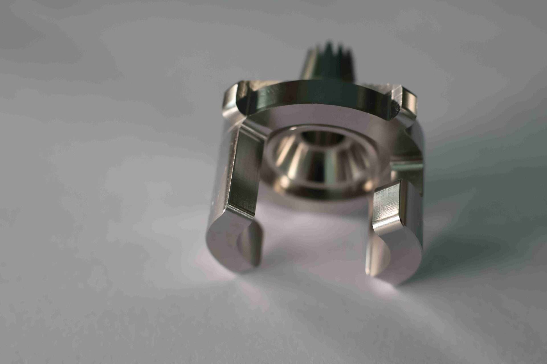
Achieving reliable CNC hole drilling accuracy means controlling how closely a finished hole’s position, diameter, and geometry match the design specification. Standard CNC machining centers achieve positional tolerances in the range of ±0.01–0.05 mm, while precision methods like reaming or boring push tighter. Accuracy depends on spindle condition, tooling quality, material properties, and machine rigidity, all of which can be controlled through proper setup, toolpath programming, and process selection.

What Is CNC Hole Drilling Accuracy and How Does the Process Work?
CNC hole drilling accuracy measures how precisely a finished hole matches its specified position, diameter, and geometry on the design drawing.
Three dimensions define that precision. Positional accuracy describes where the hole center lands relative to the programmed coordinates. Diameter accuracy measures how close the finished bore is to the nominal size. Geometric accuracy covers roundness, cylindricity, and perpendicularity, the shape of the hole, not just its location or size. A hole can land in the right place and still be out of spec if it’s oval or tilted.
What Is the CNC Drilling Process Step-by-Step?
- CAD/CAM programming: The part geometry is modeled in CAD, then CAM software generates the toolpath, defining hole coordinates, depth, feed rate, and spindle speed.
- Tool selection: Drill diameter, point angle, coating, and material grade are chosen to match the workpiece material and tolerance requirement.
- Workpiece fixturing: The part is clamped or held in a vise, collet, or custom fixture to eliminate movement during cutting.
- Spindle engagement: The machine positions the drill over the programmed coordinate and begins the plunge at the specified feed and speed.
- Feed and speed execution: The CNC controller maintains programmed parameters throughout the cut, managing chip evacuation and heat buildup.
- Inspection: Hole position, diameter, and geometry are verified using CMM, bore gauges, or optical measurement, either in-process or after the operation.
For a closer look at spindle mechanics and tooling design, the site’s existing CNC hole drilling technology content covers those fundamentals in detail.
Key Differences Between Drilling, Reaming, and Boring Operations
Drilling, reaming, and boring each serve a different role, and understanding that distinction is central to specifying the right process for a given tolerance.
Drilling removes the bulk of the material. It creates the hole but leaves a relatively rough wall finish and can introduce minor positional deviation as the drill tip walks on entry.
Reaming follows drilling to refine diameter and surface finish. A reamer removes a small amount of stock, typically fractions of a millimeter, and produces a tighter, smoother bore. It corrects diameter but does not correct position.
Boring uses a single-point tool to correct both geometry and position. It is the right choice when a hole must be repositioned or when roundness and perpendicularity tolerances are tight enough that drilling and reaming alone cannot meet them.
The tighter your CNC hole drilling accuracy requirement, the more likely you need a multi-step sequence, drill to rough size, ream to diameter, bore to final position and geometry.
Tolerance Standards and Accuracy Specifications for CNC Hole Drilling
Three frameworks govern CNC hole drilling accuracy internationally: ISO 286, ANSI B4.1, and DIN 7154, and choosing the wrong one when sourcing across borders causes costly rework.
How ISO, ANSI, and DIN Tolerance Standards Compare for Hole Accuracy
ISO 286 defines hole tolerances using International Tolerance (IT) grades, numbered from IT01 through IT18. The lower the grade number, the tighter the allowable deviation, IT5 demands far more precise tooling and process control than IT10. Grade selection directly determines which cutting tools, boring heads, and inspection methods a shop must use, so specifying the IT grade on your drawing is not optional.
ANSI B4.1 uses inch-based fit classifications, clearance, transition, and interference, while DIN 7154 applies the same three fit categories in metric. Both systems describe how a shaft and hole relate dimensionally, but the tolerance bands assigned to each fit class differ between the two standards. An engineer who specifies a clearance fit without naming the governing standard leaves the machinist to guess, which is a real risk when sourcing parts internationally across metric and inch-based supply chains.
When ordering small precision parts from an offshore supplier, always state the standard explicitly on your technical drawing, ISO, ANSI, or DIN, alongside the fit class and nominal diameter.
What Hole Tolerances Are Realistic for Different CNC Machine Types?
Machine category sets the ceiling for what tolerance is achievable in production. Standard 3-axis machining centers handle general-purpose work at moderate tolerance bands, suitable for clearance fits in structural assemblies. 5-axis machines, such as those MFG SOLUTION operates, hold tighter tolerances because simultaneous multi-axis movement reduces repositioning error and stack-up across compound hole geometries. Precision boring machines sit at the top of the range, capable of ultra-tight tolerances for bearing bores and hydraulic valve bodies where any deviation causes functional failure.
ISO 9001:2015 and IATF 16949 quality systems require documented tolerance verification at each production stage, every measured hole must be recorded and traceable for audit. For automotive and medical device buyers, this documentation is not a courtesy; it is a contractual requirement. Manufacturers certified to both standards, as MFG SOLUTION is, provide the audit-ready process records that compliance-driven procurement teams need before approving a supplier.
What Factors Affect CNC Hole Drilling Accuracy and How Do You Diagnose Them?
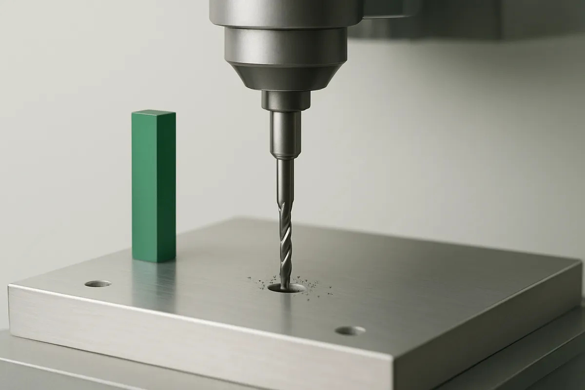
Spindle runout, tool wear, and incorrect feed rates are the three root causes that account for most CNC hole drilling accuracy failures on the shop floor.
How Spindle Runout, Tool Wear, and Feed Rate Impact Drilling Accuracy
Spindle runout occurs when bearing wear or tool holder imbalance forces the drill to rotate off-center, cutting an eccentric path. The result is an oversized hole diameter and degraded roundness, two defects that compound downstream assembly problems. Detect runout by mounting a dial indicator at the spindle nose and rotating the spindle slowly; any needle deflection beyond your tolerance band flags a bearing or holder problem that needs correction before production continues.
Tool wear progresses in stages. Edge rounding reduces cutting efficiency and increases heat, which causes the hole diameter to drift. As wear reaches the chisel edge, positional accuracy drops and surface finish deteriorates sharply. Controlling coolant flow is a direct mitigation, proper lubrication slows edge degradation and removes heat before it distorts the workpiece. For a full breakdown of fluid selection, see MFG SOLUTION’s guide to CNC coolants and lubricants.
Feed rate and cutting speed interact in ways that each degrade accuracy through a different mechanism. A feed rate set too high deflects the drill laterally, producing oversized, out-of-round holes. A cutting speed set too low increases rubbing instead of cutting, generating heat that accelerates wear. Neither extreme is safe, both require dialing in together against the specific material and drill geometry.
Common Causes of Chatter and Tool Breakage, and How to Fix Them
Three failure modes account for the majority of drilling defects, and each has a distinct diagnostic path.
- Chatter: Visible as a repeating wave or spiral pattern on the hole wall. The fix starts with increasing system rigidity, check tool overhang, fixture clamping, and workpiece support, then adjust spindle speed away from the resonant frequency causing the vibration.
- Tool breakage: Usually caused by excessive chip load or interrupted coolant flow. Inspect chip formation: long, stringy chips signal too-low feed; packed chips in the flutes signal inadequate coolant or too-deep a peck cycle. Reduce depth-per-peck and verify coolant pressure before resuming.
- Positional error: When drilled holes land off-location, the diagnosis starts at the datum, check fixture repeatability and confirm the part is seating consistently across cycles. A worn or incorrectly torqued fixture introduces positional drift that no programming correction can fully compensate.
How Material Properties Influence Hole Accuracy
Material hardness, thermal conductivity, and chip formation behavior all affect how accurately a hole can be drilled. Soft, ductile materials like aluminum tend to produce long, stringy chips that pack in the flute and push the drill off-center if chip evacuation is not managed. Hard materials like stainless steel or titanium generate significant cutting heat, which causes thermal expansion in both the tool and the workpiece, shifting the effective hole diameter during the cut.
Brittle materials such as cast iron or certain ceramics fracture rather than shear, which can cause micro-chipping at the hole entry and exit that degrades geometric accuracy. For each material class, the correct combination of point geometry, coating, and coolant strategy is different. Matching those variables to the workpiece is as important as machine selection when specifying a process that must hold tight tolerances.
How Accuracy Compares Across Different Types of CNC Machines
Machine type sets the hard limit on CNC hole drilling accuracy, 5-axis machining centers outperform 3-axis setups on complex parts, while hobby machines suit only non-critical work.
3-Axis vs. 5-Axis CNC Machines: Accuracy Differences for Hole Drilling
3-axis machining centers handle the majority of through-hole and tapped-hole work because their fixed-axis geometry keeps compound angular error low during a single-face operation. The limitation appears when a part requires holes on multiple faces, each repositioning introduces a datum shift, and those small positional offsets accumulate across setups.
5-axis machines eliminate most of that risk for complex parts. By drilling compound-angle holes in a single setup, the machine never transfers the datum to a new fixture position. Fewer datum transfers means fewer accumulated positional errors, that’s the core accuracy advantage over 3-axis when part geometry demands holes at multiple angles or faces.
For straightforward prismatic parts with holes on one face, a well-maintained 3-axis center delivers equivalent results at lower cycle cost. The 5-axis advantage is specific to geometric complexity, not a universal upgrade.
How Machine Rigidity and Spindle Specifications Set the Accuracy Ceiling
Frame mass, linear guide type, and ballscrew preload determine how much a machine deflects under cutting load. A rigid frame absorbs the radial forces a drill generates; a lighter frame allows micro-deflection that shifts hole position and widens diameter tolerance.
Spindle specifications work alongside frame rigidity. Bearing class, maximum RPM rating, and runout tolerance control how true the tool rotates. A precision spindle with tight runout keeps the drill on-center; a wider-tolerance spindle lets the cutting edge wander, producing oversized or out-of-round holes.
Hobby and benchtop CNC machines combine all three weaknesses, lower frame stiffness, wider spindle tolerances, and less precise ballscrews. Those machines are suitable for non-critical holes in soft materials, but they cannot hold the positional and diameter tolerances that electronics, automotive, or medical components require. MFG SOLUTION’s production floor runs 5-axis CNC machines and 20 automatic lathes built to industrial frame and spindle standards, which is why the facility holds ISO 9001:2015, IATF 16949, and ISO 13485:2016 certification across its full process range.
Methods That Improve CNC Drilling Accuracy and How to Choose Between Them
Reaming, boring, and EDM are the three main process upgrades that improve CNC hole drilling accuracy, each targets a different error type and carries a different cost profile.
When to Use Reaming, Boring, or EDM for Improved Hole Accuracy
Reaming is the first step up from standard drilling. A reamer corrects diameter and surface finish by removing a small, controlled amount of material, but it follows the existing hole centerline exactly. If the drill walked or the hole is mislocated, reaming will not fix that. Use reaming when your diameter tolerance is tight and the drill operation already placed the hole accurately.
Boring corrects both diameter and position simultaneously. A single-point tool mounted on a rigid boring bar cuts on one side of the hole, allowing the machine to offset the centerline to its true position. That mechanism, controlled, asymmetric material removal, is what makes boring more accurate than reaming for holes that are out of round or mislocated. For a detailed look at the boring process, MFG SOLUTION’s CNC boring process content covers the setup parameters in depth.
EDM (electrical discharge machining) uses controlled electrical sparks rather than cutting forces to erode material. No mechanical contact means no tool deflection, making EDM the right choice for hardened materials or micro-holes where even a rigid boring bar would flex and introduce error.
The cost-benefit logic follows a clear progression. Standard drilling is the most cost-efficient baseline. Reaming adds moderate cycle time and tooling cost to achieve diameter precision. Boring adds setup complexity and machine time to correct position. EDM sits at the premium tier, appropriate only when hardness or geometry rules out mechanical methods entirely.
The practical decision framework: identify your tightest tolerance first, then determine whether positional or diameter accuracy is the binding constraint. Select the minimum-intervention method that meets spec. Over-engineering, running a boring operation when reaming would suffice, inflates cost without improving function. At MFG SOLUTION, our 60+ engineering professionals apply this kind of process selection logic across CNC turning, Swiss lathe, and mill-turn operations to match the right method to each part’s actual requirements.
Frequently Asked Questions
What is the difference between positional accuracy and diameter accuracy in CNC drilling?
Positional accuracy describes how precisely the drill lands on the intended X/Y coordinate; diameter accuracy describes how close the finished hole size is to the specified dimension. Both matter independently. A hole can be perfectly centered but undersized, or correctly sized but offset from its true position. Tight tolerances on both dimensions are required for parts where fasteners, pins, or press-fit components must align and seat correctly.
How does coolant affect CNC hole drilling accuracy?
Coolant directly improves accuracy by controlling heat buildup, which is the primary cause of drill bit expansion and dimensional drift during deep or high-speed drilling. Proper coolant flow also flushes chips from the hole, preventing re-cutting that enlarges diameter and roughens the bore wall. Through-spindle coolant delivery is the most effective method for deep holes where surface flooding cannot reach the cutting zone.
Can a standard CNC drill achieve the same accuracy as a reamed hole?
No, a standard CNC drill typically holds diameter tolerances in the ±0.05 mm range, while reaming can achieve ±0.01 mm or tighter. Drilling is a material-removal operation; reaming is a finishing operation that corrects diameter and surface finish after the hole exists. For precision fits, bearing bores, hydraulic ports, or medical device housings, reaming after drilling is the standard process sequence, not an optional upgrade.
How do you verify hole accuracy after CNC drilling?
Hole accuracy is verified using calibrated gauging tools matched to the tolerance class of the feature. Pin gauges confirm go/no-go diameter limits for tight-tolerance holes. Air gauging measures bore diameter without contact and is common in high-volume automotive and medical production. Coordinate measuring machines (CMMs) verify positional accuracy by mapping hole center locations against the part’s datum reference frame. Each method suits a different tolerance range and production volume.
What role does fixturing play in maintaining CNC hole drilling accuracy across a production run?
Fixturing is one of the most overlooked contributors to consistent CNC hole drilling accuracy in production. A fixture that seats the part identically on every cycle ensures the datum reference frame stays constant, so programmed hole coordinates translate correctly to the physical part. Fixture wear, loose clamping, or inconsistent seating forces introduce positional drift that compounds across a batch. For high-volume runs, dedicated hard tooling fixtures with locating pins and repeatable clamping torque are standard practice to maintain positional accuracy from the first part to the last.
Conclusion
CNC hole drilling accuracy depends on three controllable variables: tool selection, machine rigidity, and process sequencing. Skipping a pilot hole on deep features, ignoring spindle runout, or using a worn drill bit each introduce errors that compound, and no inspection step corrects a hole that was drilled wrong from the start.
Two actions make the biggest difference: specify your tolerance class before choosing a process (drilling, reaming, or boring), and confirm your machine’s actual positional accuracy with a test piece before committing to a production run.
If your next part requires holes held to ±0.01 mm or tighter, submit your drawing to MFG SOLUTION, you’ll have a process recommendation and quote within 8 hours.
Recommended Articles
Explore more from our content library: