
2026-07-13
How to Implement Swiss Machining for Complex Small Parts
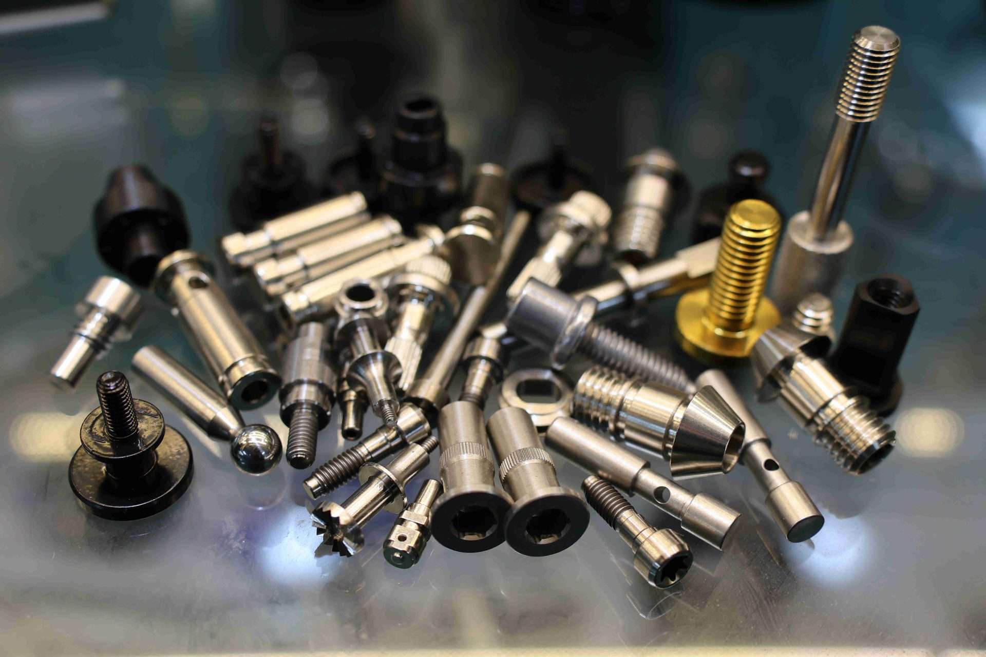
To implement Swiss machining, select a sliding-headstock CNC Swiss lathe sized for your part diameter (typically 1–38mm), program toolpaths using CAM software optimized for live tooling, and qualify your first run against tolerance targets—often ±0.001″ or tighter. Swiss machining excels at long, slender, high-precision parts in a single setup, making it the go-to process for medical, aerospace, and electronics components where conventional CNC turning can’t hold tolerances without secondary operations. According to Xometry’s overview of Swiss machining, the process is especially effective for parts requiring multiple operations in a single cycle.
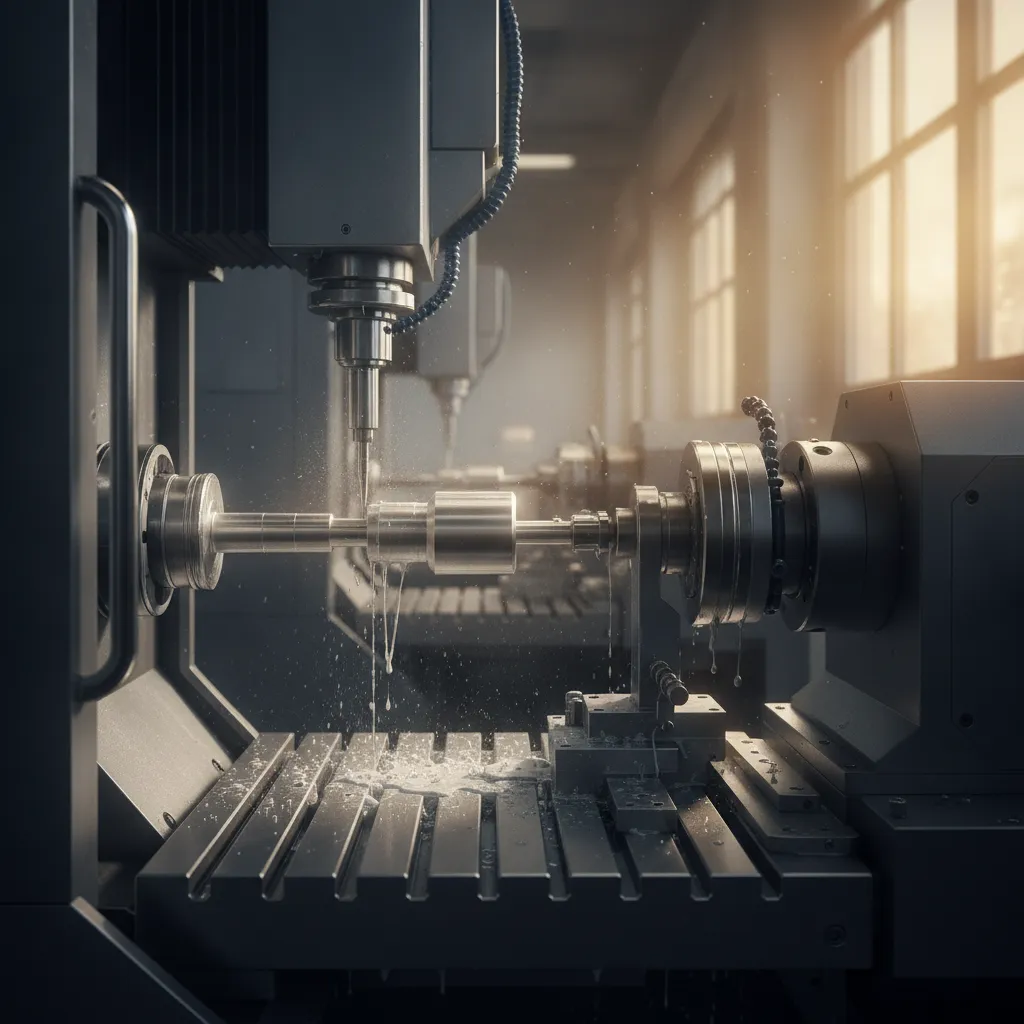
What You’ll Need Before You Implement Swiss Machining
Before you implement Swiss machining, you need a sliding-headstock lathe, bar feeder, guide bushing, Swiss-capable CAM software, and an operator trained in multi-axis CNC turning.
Swiss machines handle bar stock from 1mm to 38mm in diameter. Confirm your part envelope fits that range before purchasing equipment or committing to a production contract—a part at 40mm diameter simply cannot run on a Swiss lathe, regardless of other capabilities.
“Swiss-type lathes represent one of the most significant advances in precision turning—the guide bushing fundamentally changes what’s achievable on slender parts by eliminating unsupported length at the cutting zone.” — Dr. John Ziegert, Professor of Mechanical Engineering, Clemson University
Equipment and Tooling Checklist
- Sliding-headstock Swiss lathe (Citizen, Tsugami, or Star are the established brands): the sliding headstock advances bar stock through a fixed guide bushing, keeping unsupported length to 1–2× the bar diameter and eliminating the deflection that defeats conventional turning on slender parts.
- Guide bushing: supports bar stock at the cutting point. Without it, vibration increases and tolerances—often ±0.0002″ to ±0.001″—become impossible to hold.
- Bar feeder: automates stock loading for unattended runs. Manual loading defeats the cycle-time advantage Swiss machining offers.
- High-pressure coolant system: chip evacuation in deep-bore and cross-drilling operations depends on coolant pressure. Low-pressure systems allow chips to re-cut and damage surface finish. Review your coolant specification against your material before setup—our CNC coolants and lubricants guide covers fluid selection by alloy type.
Software and Programming Requirements
Your CAM platform must support Swiss-specific toolpath strategies: live tooling, back-spindle operations, and gang-tool layout. Mastercam Swiss and ESPRIT both handle these natively and generate synchronized multi-spindle code that generic turning post-processors cannot produce.
Operators need solid G-code literacy for CNC turning, a clear understanding of tool offsets, and ideally hands-on time with multi-axis turning centers before touching a Swiss program. Tolerance stack-up on a 12-part gang setup compounds fast—our machining tolerances explained resource walks through how offset errors propagate across simultaneous tool engagements.
Implement Swiss Machining: A Step-by-Step Transition from Conventional CNC
To implement Swiss machining successfully, select the right parts first, then work through machine setup, programming, inspection, and production validation in sequence. Shops that implement Swiss machining in a structured, phased approach consistently report fewer scrapped first articles and faster time-to-production than those that rush the transition.
Selecting the Right Parts to Run First
Start with parts that have a length-to-diameter (L/D) ratio greater than 3:1—these are exactly where conventional CNC turning loses rigidity and Swiss excels. Diameter tolerances of ±0.0005″ to ±0.001″ and features that currently require two or more setups (turning, cross-drilling, threading) are strong indicators that a part belongs on a Swiss lathe.
Avoid starting with parts that have large-diameter flanges or require significant facing operations—those geometries reduce the guide bushing’s effectiveness and are better suited to CNC mill-turn or conventional turning first.
- List all parts with L/D > 3:1 from your current routing sheets.
- Flag any part requiring three or more operations across separate setups.
- Prioritize parts with diameter tolerances tighter than ±0.001″, these show the clearest cost-per-part improvement after transition.
Programming the Sub-Spindle and Live Tooling
Swiss machine setup begins with loading bar stock through the guide bushing, setting collet grip pressure to match bar diameter and material, positioning gang-tool slides, and configuring the back spindle for cutoff and secondary operations. Each step affects dimensional output directly, a misaligned gang slide by even 0.001″ shifts feature position on every part in the run.
Programming a Swiss lathe requires a fundamental mental model shift: Z-axis moves are programmed relative to the guide bushing, not the chuck face as in conventional CNC. Sub-spindle synchronization, when the back spindle grips the part for secondary operations, must be programmed explicitly with timed dwell and speed-match commands, or you risk part pull-out and scrap.
- Rewrite Z-axis reference points relative to the guide bushing face before transferring any existing CNC program.
- Add explicit sub-spindle speed-match and grip commands before every cutoff sequence.
- Simulate the full cycle in CAM software to catch tool-path collisions between gang tools and the sub-spindle.
“When manufacturers implement Swiss machining for the first time, the most common programming error is carrying over Z-axis reference conventions from conventional turning. That single mistake accounts for the majority of first-run crashes.” — Mark Cicoria, Senior Applications Engineer, Citizen Machinery America
First-Article Inspection and Process Sign-Off
Measure OD, ID, length, and all feature positions against the engineering print before releasing any production quantity. When setup is correct, Swiss-machined parts routinely achieve a Cpk greater than 1.67 on diameter, a process capability benchmark that satisfies both IATF 16949 automotive and ISO 13485 medical device requirements. According to the American Society of Mechanical Engineers (ASME), process capability indices above 1.67 are the accepted standard for safety-critical precision components.
Before full production release, confirm bar feeder cycle time, chip evacuation rate, and coolant pressure. A 10mm medical pin, for example, typically cycles in 15–45 seconds on a Swiss lathe, validate that your bar feeder keeps pace without starving the spindle. MFG SOLUTION’s Swiss lathe operations run this exact validation sequence, backed by ISO 13485:2016 and IATF 16949 certification, so every first article is traceable and auditable before a single production part ships.
- Record OD and ID measurements at three points along part length, not just at the tip.
- Calculate Cpk from the first 30 parts; target >1.67 before approving the run.
- Check chip evacuation visually and confirm coolant pressure holds steady throughout the cycle before signing off.
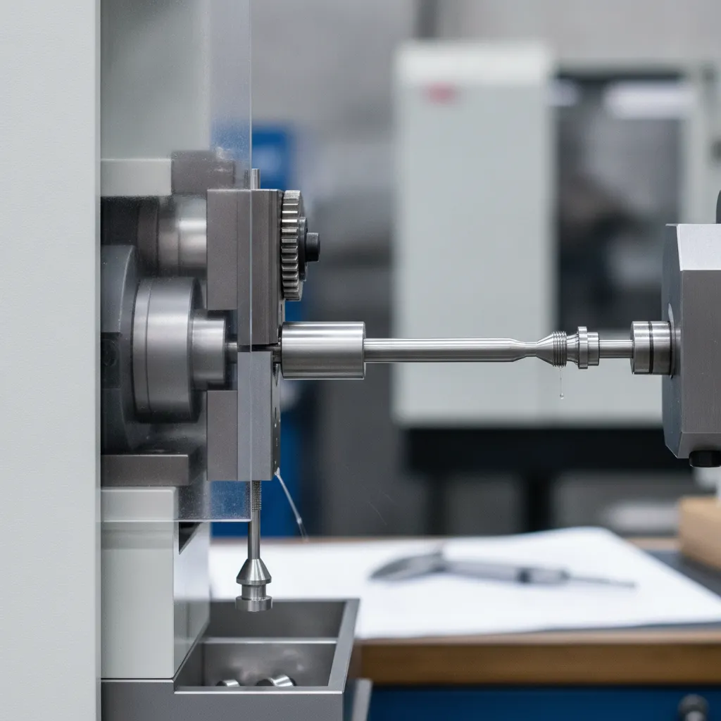
Choose Materials and Part Geometries That Maximize Swiss Machining Output
Free-machining metals and long-slender geometries under 38mm diameter return the most value when you implement Swiss machining in production.
The guide bushing is the reason material selection matters so much. It supports bar stock within 1–2 diameters of the cutting tool, so materials that machine cleanly without generating excessive heat or tool pressure hold tolerance without deflection. The best performers are: For more information, see Thegoodcode.
- 303 and 316L stainless steel, sulfur additives in 303 improve chip breaking; 316L’s corrosion resistance suits medical implant-adjacent parts without sacrificing machinability.
- Titanium Grade 5 (Ti-6Al-4V), harder to cut than stainless, but the bushing’s close support prevents the flex that causes chatter on conventional lathes.
- Brass C360, the highest free-machining rating of any copper alloy; it clears chips fast and lets cycle times drop significantly.
- Aluminum 6061 and 7075, light, fast to cut, and ideal for connector bodies and miniature valve stems where weight matters.
- PEEK, the guide bushing prevents the polymer from deflecting under tool pressure, which is the primary failure mode on conventional lathes.
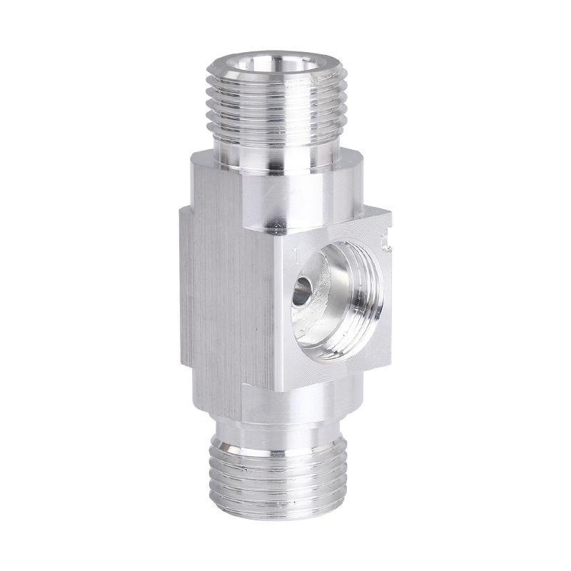
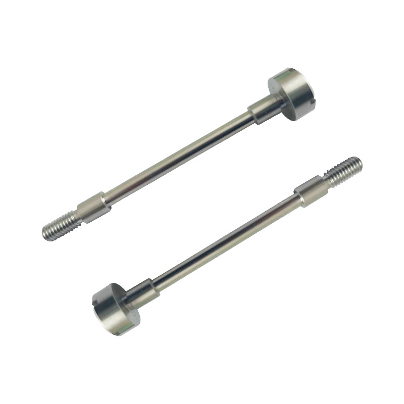
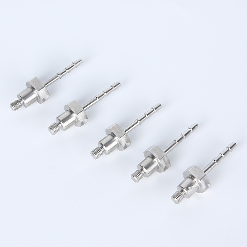
The geometry sweet spot is any part with a length-to-diameter (L/D) ratio above 3: shafts, pins, bone screws, and cannulas, connector bodies, and miniature valve stems. These profiles are exactly where Swiss outperforms conventional turning because the bushing eliminates the unsupported length that causes dimensional drift. Manufacturers who implement Swiss machining for medical device production consistently cite this geometry advantage as the primary driver of yield improvement.
When tooling and coolant are optimized, Swiss-machined parts routinely hold surface finishes of Ra 0.4–0.8 µm without secondary grinding—a direct cost saving on finishing operations. MFG SOLUTION’s Swiss lathe process targets this finish range on certified production runs for medical and automotive customers.
Swiss Machining vs. Conventional CNC Turning: When to Use Each
Swiss wins on parts under 38mm diameter with an L/D ratio above 3; multi-axis CNC turning wins on larger-diameter, shorter parts where the guide bushing adds no benefit.
A concrete crossover example: a 12mm-diameter shaft at 60mm long (L/D = 5) belongs on a Swiss lathe. A 40mm-diameter housing at 25mm long (L/D = 0.6) belongs on a multi-axis CNC turning center—the bushing would restrict access and add no stability benefit on a part that short and wide.
For threaded shafts and other features requiring tight-pitch thread accuracy on slender stock, Swiss also holds the advantage because tool pressure is absorbed by the bushing rather than transferred to the part. Multi-axis turning handles complex face features and large-bore work where Swiss simply cannot reach. For a detailed technical comparison, Xometry’s Swiss machining resource provides side-by-side capability breakdowns that help engineers decide when to implement Swiss machining versus conventional turning.
Avoid These Common Swiss Machining Implementation Mistakes
The five mistakes below account for most of the scrap, crashes, and rework shops encounter when they first implement Swiss machining.
Ignoring guide bushing clearance is the fastest way to produce out-of-tolerance ODs. Running bar stock with more than 0.0005″ clearance in the bushing causes chatter and dimensional scatter. Match the bushing bore to the bar diameter within 0.0002″, measure every new bar lot before loading.
Programming Z-axis like a conventional lathe crashes tools or produces wrong part lengths on the first run. On a Swiss lathe, Z-moves reference the guide bushing position, not the chuck. Operators coming from conventional turning must remap their mental model before touching the control, this is not a setting you adjust after a crash.
Underestimating the operator learning curve delays production schedules by weeks. Most operators need 40–80 hours of supervised run time before running a Swiss machine unsupervised. Build that time explicitly into your implementation timeline and budget; skipping it shifts the cost to scrap and downtime.
Using wrong coolant pressure destroys tooling on stainless and titanium. Swiss machining those materials requires high-pressure coolant at 500–1,000 PSI directed at the guide bushing and cutting zone. Standard 100 PSI flood coolant causes built-up edge and accelerated tool failure. Review your CNC coolants and lubricants setup before the first production run.
Skipping a bar stock straightness spec amplifies runout through the entire process. Swiss machines magnify any bar deviation, require straightness of 0.010″ per foot or better from your supplier, and verify incoming stock with a V-block and dial indicator.
Troubleshooting Chatter and Out-of-Tolerance Diameters
Chatter on a Swiss lathe almost always traces back to bushing clearance or bar runout, check both before adjusting spindle speed or feed rate. If ODs drift out of tolerance mid-bar, the bar stock likely exceeds the 0.010″ per foot straightness limit and is deflecting as it feeds through the bushing.
At MFG SOLUTION, our Swiss lathe operations run bar stock matched to bushing bore within 0.0002″ and use high-pressure coolant as standard, the same process controls that support our ISO 9001:2015 and IATF 16949 certifications. When a diameter problem persists after correcting clearance and straightness, audit the coolant pressure and tool nose radius before making program changes.
Calculate the ROI of Swiss Machining Before You Commit
Swiss machining pays for itself fastest on high-volume, long-slender parts—but only if your geometry, volumes, and per-piece cost targets align with the process.
A new Swiss CNC lathe runs $150,000–$400,000 depending on axis count and bar capacity; used machines start around $60,000 and are a realistic entry point for a first installation. Budget the higher end if you need live tooling, sub-spindle capability, or bars above 20mm diameter.
Cycle time savings are where the math gets compelling. Swiss consolidates 3–5 conventional setups into one pass, cutting total part lead time by 40–60% for qualifying geometries. A medical stainless pin that requires turning, drilling, and chamfering on conventional equipment might take 4.2 minutes across three setups; on a Swiss lathe, the same pin runs in 1.6 minutes—complete, in one cycle.
That difference drives the break-even. A shop producing 50,000 precision pins per month at $0.80 per piece in setup cost on conventional turning can recover a $200,000 Swiss investment in under 18 months when Swiss reduces the per-piece cost to $0.35. The savings of $0.45 per piece across 50,000 monthly units generates $22,500 per month—covering the machine in roughly 9 billing cycles, before accounting for reduced scrap and secondary operations.
“The ROI calculation for shops that implement Swiss machining is almost always driven by setup consolidation, not raw cycle time. Eliminating three setups on a high-volume part changes the economics entirely.” — Patricia McGarr, Manufacturing Economist, Society of Manufacturing Engineers
When Swiss Machining Pays Off vs. When It Doesn’t
Deciding whether to implement Swiss machining comes down to three disqualifying conditions. Short, fat parts with a length-to-diameter ratio below 2:1 don’t benefit from guide bushing support—conventional turning handles them more economically. Prototype runs under 500 pieces rarely justify the setup time and tooling investment. Materials with poor bar straightness, such as some annealed alloys, cause frequent bushing changes that erode the cycle time advantage entirely.
If your parts sit near the tolerance boundary between conventional and Swiss, review your precision tolerance stackup analysis before committing. Parts holding ±0.0005 inches or tighter on features like thread runout or bore concentricity are where Swiss delivers measurable yield improvement—and where MFG SOLUTION’s Swiss lathe capability, backed by ISO 9001:2015 and IATF 16949 certification, gives procurement teams a documented, auditable process rather than a verbal guarantee. The National Institute of Standards and Technology (NIST) publishes dimensional metrology guidelines that are directly applicable when validating whether your tolerance requirements justify the decision to implement Swiss machining.
Frequently Asked Questions
What does ‘Swiss’ mean in CNC machinist job descriptions?
“Swiss” refers to experience operating a Swiss-type lathe, a sliding-headstock turning machine designed for small-diameter, high-precision parts. The term originates from Swiss watchmaking, where the machine style was developed to produce miniature components. In job postings, it signals that a machinist can set up and run bar-fed Swiss lathes, program multi-axis tool paths, and hold tolerances commonly ranging from ±0.0002 in to ±0.001 in.
How long does a Swiss machining process take per part?
Cycle times per part typically run from a few seconds to several minutes, depending on part complexity and diameter. Simple turned components on a Swiss lathe can complete in under 30 seconds at high bar-feed rates. Complex parts requiring milling, threading, and cross-drilling in a single cycle take longer, but because Swiss machines combine multiple operations in one pass, total throughput per shift is high compared to conventional turning.
What industries use Swiss machining most heavily?
Medical device, aerospace, automotive, and electronics manufacturers are the heaviest users of Swiss machining. Medical applications include bone screws, cannulas, and catheter components. Automotive suppliers use Swiss lathes for fuel injector pins and sensor housings. Electronics manufacturers rely on them for miniature connectors and contacts where tight tolerances and high volume are both required.
Can Swiss machines run without a guide bushing, and when should you remove it?
Yes, most modern Swiss-type lathes can operate in guidebushingless mode, and removing it is the right call for short parts or bar stock already at finished diameter. Without the guide bushing, the distance between the chuck and cutting tool shortens, which reduces material waste from the remnant bar stub. The tradeoff is reduced rigidity on long, slender parts, so guidebushingless mode suits parts with a length-to-diameter ratio below roughly 3:1.
How do you qualify a supplier when you need to implement Swiss machining but lack in-house equipment?
When you need to implement Swiss machining but don’t own the equipment, evaluate suppliers on four criteria: machine brand and axis count (Citizen, Tsugami, or Star with live tooling and sub-spindle), quality certifications relevant to your industry (ISO 13485 for medical, IATF 16949 for automotive), first-article inspection documentation with Cpk data, and lead time from drawing submission to shipped parts. Request a sample run of 30 pieces before committing to production volumes, and verify that the supplier’s bar diameter range covers your part geometry.
Conclusion
Implementing Swiss machining successfully comes down to three decisions made before the first bar feeds: selecting the right part geometry (slender, small-diameter, high-complexity), choosing materials that machine cleanly at high spindle speeds, and building quality checkpoints, dimensional inspection, surface finish verification, and tool wear monitoring, into the production run from the start. Manufacturers who implement Swiss machining with these fundamentals in place consistently achieve faster break-even and higher first-pass yield than those who treat it as a simple equipment swap.
If your parts fall under 38mm in diameter and your current supplier is quoting 4–6 week lead times, that gap is worth closing. MFG SOLUTION delivers Swiss lathe machined parts with quotes within 8 hours and shipment within 3 days, certified to ISO 9001:2015, ISO 13485:2016, and IATF 16949. Submit your part drawing at mfg-solution.com and get a priced quote before your next business day starts.
Recommended Articles
Explore more from our content library:
- How to Validate Coolant CNC Performance in High-Speed Ops
- How to Specify CNC Workholding for Optimal Part Accuracy
- How to Reduce Deburring Costs CNC: Save 25–40% on Finishing
- How to Manage Tolerance Stackup in Precision Parts
- CNC Threading Optimization for Small Parts