
2026-10-17
CNC Machining for Industrial Gearbox and Transmission Components: Shafts, Bearing Housings, Alignment and Dimensional Accuracy
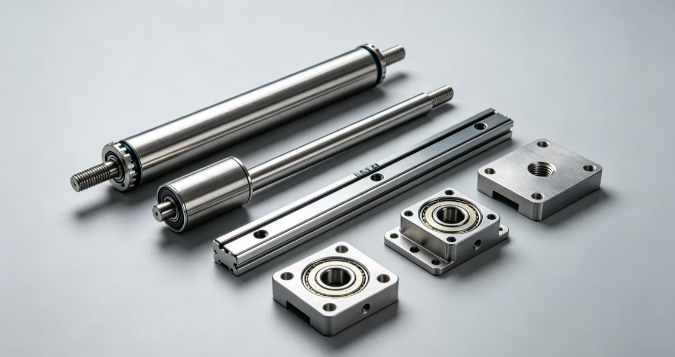
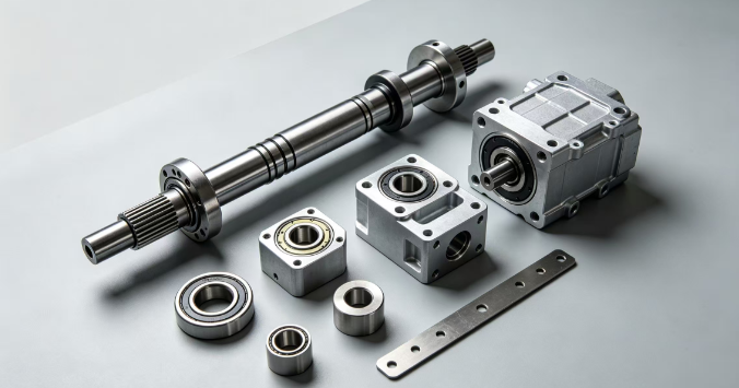
SEO Title
CNC Machining for Industrial Gearbox and Transmission Components
Meta Description
Discover how CNC machining improves industrial gearbox shafts, bearing housings, transmission interfaces and precision components through material selection, tolerance control, surface finishing and quality inspection.
Introduction: Why Precision Matters in Gearbox Manufacturing
Industrial gearboxes and transmission systems convert speed and torque, transfer mechanical power, and maintain controlled motion across a wide range of applications. From packaging machinery and conveyor systems to industrial pumps, machine tools and automated production equipment, their reliability depends on the interaction of multiple mechanical components.
A gearbox may contain shafts, bearing housings, mounting plates, spacers, bushings, adapters, covers and custom interfaces. Although some of these components appear relatively simple, their dimensional relationships can influence bearing alignment, vibration, friction, noise, wear and assembly repeatability.
For equipment manufacturers, selecting a suitable CNC machining partner is therefore about more than producing individual parts to a nominal dimension. The supplier must understand how each component fits into the assembly, which features are functionally critical, how the selected material behaves during machining, and which inspection methods can verify the finished part.
CNC machining is well suited to custom gearbox and transmission components because it supports accurately controlled bores, concentric cylindrical features, mounting patterns, keyways, threaded holes and complex milled surfaces. Depending on geometry and production volume, CNC turning, milling, multi-axis machining and secondary finishing operations can be combined into an appropriate manufacturing route.
At MFG SOLUTION, custom manufacturing projects can be evaluated according to part geometry, material, tolerances, finishing requirements and production quantity. This guide explains the engineering considerations that industrial equipment manufacturers should address when sourcing precision gearbox and transmission components.
1. Common CNC-Machined Gearbox and Transmission Components
1.1 Transmission shafts and drive shafts
Shafts transmit torque between motors, gears, couplings, bearings and other rotating components. Their geometry may include several diameter sections, bearing journals, shoulders, grooves, keyways, cross-holes and threaded ends.
The important consideration is not simply whether every diameter meets its individual tolerance. The relationship between functional surfaces must also be controlled.
For example, a shaft with multiple bearing journals may require coordinated control of diameter, concentricity-related relationships, runout and shoulder position. If the bearing surfaces are misaligned, the assembly may experience uneven loading or unwanted vibration.
CNC turning is commonly used to create cylindrical features, while milling, drilling and slotting operations produce additional functional geometry.
For complex shafts, the manufacturing plan should identify:
- Critical bearing and seal diameters.
- Shoulder locations and axial distances.
- Keyway dimensions and orientation.
- Thread specifications and engagement length.
- Surface finish requirements on sliding or rotating interfaces.
- Runout and other specified geometric tolerances.
When these features are distributed across several setups, the supplier should consider how workholding and datum transfer affect final accuracy.
1.2 Bearing housings and bearing blocks
Bearing housings locate and support bearings while connecting rotating components to the surrounding machine structure.
Their critical features may include bearing bores, mounting faces, bolt patterns, lubrication passages and retaining-ring grooves. Bore size is important, but so are bore position, axis orientation and the relationship between the bore and the mounting datum.
A bearing housing can have a correctly sized bore yet still create assembly problems if the bore axis is not positioned correctly relative to the base.
For these components, CNC milling and boring operations should be planned around the functional datums. Where several bores must align, machining them in a common setup can reduce the accumulation of setup-related errors when the part geometry and machine capacity permit.
Learn more about CNC machining services and how machining strategies can be selected for housings, structural parts and precision interfaces.
1.3 Gearbox housings and mounting plates
Gearbox housings support internal mechanisms and provide mounting interfaces for motors, covers, bearings and external equipment.
Depending on the design, a housing may require:
- Flat mounting and sealing surfaces.
- Precisely positioned bolt holes.
- Bearing pockets and locating shoulders.
- Threaded holes for covers and accessories.
- Clearance pockets and internal cavities.
- Controlled wall thickness and dimensional stability.
For complex housings, the design should distinguish between functional surfaces and noncritical exterior surfaces. This helps allocate machining time and inspection effort where they provide the greatest value.
Aluminum housings may be attractive when weight reduction is important, while steel or other materials may be more suitable for specific loading, wear or environmental requirements.
1.4 Bushings, spacers and precision adapters
Bushings and spacers control clearance, positioning and the relationship between adjacent components. Adapters connect components with different mounting patterns, diameters or interface geometries.
These parts are often small, but their function may depend on accurate thickness, bore diameter, parallelism, thread quality or concentricity-related requirements.
For repeat orders, a documented process and consistent measurement method are important because minor variations can affect assembly across an entire production batch.
CNC turning is often appropriate for rotational parts, while milling and drilling can be added for flats, mounting holes and other nonrotational features.
2. Selecting the Right CNC Machining Process
No single process is optimal for every gearbox component. The choice depends on geometry, material, tolerance, quantity and the complete sequence of manufacturing operations.
CNC turning for rotational components
Turning is suitable for shafts, sleeves, spacers, bushings and cylindrical adapters. It efficiently creates external diameters, internal bores, shoulders, grooves and threads.
For parts with multiple diameter sections, an appropriate setup can help maintain the relationship between functional cylindrical surfaces. Slender shafts may need additional support and a machining strategy that limits deflection.
CNC milling for housings and interfaces
Milling is appropriate for mounting plates, bearing blocks, brackets and housings with flat surfaces, pockets, bolt patterns and complex contours.
The process plan should consider tool access, workholding stability, material removal and the datum structure. Deep pockets and thin walls may require additional attention because cutting forces can cause deflection.
Multi-axis machining for complex geometry
Four-axis and five-axis machining can reduce the need for repeated repositioning when parts have features on multiple faces or complex spatial relationships.
Fewer setups may improve consistency between features and reduce handling time. However, multi-axis machining is not automatically the lowest-cost solution. Simple parts may be produced more economically using conventional turning or three-axis milling.
The best process is the one that achieves the required geometry and quality at a suitable total production cost.
Secondary operations and integrated production
Some components need drilling, tapping, deburring, grinding, heat treatment or surface finishing after the primary machining operation.
These steps should be considered during quotation and process planning. A component that appears inexpensive to machine may become costly if its secondary operations are difficult to coordinate or require extensive rework.
MFG SOLUTION provides CNC machining capabilities for evaluating part geometry and production requirements, with material and process choices assessed according to the actual application.
3. Material Selection for Gearbox and Transmission Parts
Material selection affects strength, machinability, wear resistance, corrosion behavior, weight, dimensional stability and cost. The correct choice depends on the loads and environment experienced by the finished component.
Carbon and alloy steels
Steel may be suitable for shafts, mounting elements and components that need strength or durability. The precise grade should be selected according to the application, loading conditions, heat-treatment requirements and design specifications.
For parts that undergo heat treatment, the manufacturing plan must account for possible dimensional changes. Critical diameters or interfaces may need finishing after heat treatment, depending on the required tolerance and process.
Stainless steel
Stainless steel can be appropriate when corrosion resistance is important. The exact grade should reflect the operating environment, mechanical requirements and machining conditions.
Stainless steel grades can differ substantially in machinability and mechanical behavior. Work hardening, tool wear and heat generation should be considered during process planning.
Explore the SS 17-4 material guide for further information about a precipitation-hardening stainless steel used in applications requiring a combination of strength and corrosion resistance.
Aluminum alloys
Aluminum alloys are useful for selected housings, covers, mounting plates and lightweight structural components.
They can offer favorable machinability and a relatively low component weight. However, the alloy, temper, wall thickness and mounting loads must be considered before substituting aluminum for steel.
Surface treatment may also be required, depending on corrosion exposure, wear, appearance or electrical requirements.
Engineering plastics and brass
Engineering plastics can be suitable for certain bushings, spacers, guides and low-load interfaces where friction, weight or electrical properties matter. Their dimensional behavior under temperature and sustained load should be evaluated carefully.
Brass may be useful for selected fittings, bushings and precision hardware. The specific alloy should be selected according to strength, wear, corrosion, conductivity and regulatory requirements.
The MFG SOLUTION materials guide provides a starting point for comparing material properties and manufacturing considerations.
4. Tolerance, Datum and Alignment Control
Dimensional accuracy becomes particularly important when a gearbox component interacts with bearings, rotating shafts, seals or mounting structures.
Define functional datums
Datums establish the reference system used to manufacture and inspect a component. For a bearing housing, the mounting face and bore axis may be central to its function. For a shaft, a specified axis or bearing journal may provide the reference for other features.
If the drawing does not clearly communicate the intended reference system, the manufacturer may interpret the same dimensions differently from the design engineer.
A good engineering review identifies which surfaces establish position and orientation during assembly.
Apply tolerances according to function
Tighter tolerances can improve fit or performance, but they may also increase machining time, inspection effort and rejection risk.
Not every feature needs the same level of precision. A bearing seat, sealing surface or locating shoulder may have different functional requirements from an external cover surface or a noncritical clearance feature.
Engineers should identify critical-to-function dimensions and specify tolerances that reflect the real assembly requirements.
Consider geometric tolerances
Depending on the design, relevant geometric controls may include:
- Flatness of mounting or sealing surfaces.
- Perpendicularity between faces and axes.
- Parallelism between reference surfaces.
- Position of mounting holes.
- Runout of rotating features.
- Cylindricity or other form controls where specified.
Geometric tolerances should be defined on the engineering drawing and interpreted in the context of the applicable GD&T standard.
For more information about process capability and inspection planning, refer to quality assurance standards for CNC machined parts.
5. Surface Finish, Wear and Heat Treatment
The surface condition of a gearbox component can influence friction, lubrication, sealing, corrosion and wear. The appropriate finish depends on how the component functions, rather than on appearance alone.
Bearing and sliding surfaces
Bearing seats, sliding interfaces and rotating contact surfaces may require controlled roughness and dimensional accuracy. The required finish should be specified according to the bearing arrangement, fit, lubrication system and component design.
A very smooth surface is not always better for every application. The correct texture depends on the contact mechanism and the manufacturer’s engineering requirements.
Sealing interfaces
Where a housing or cover forms a sealing interface, surface flatness, roughness and local defects may affect sealing performance.
Machining strategy should account for the final condition of the sealing surface, including whether a coating or other finishing operation follows machining.
Heat treatment and finishing sequence
Heat treatment may be necessary for selected steel components to achieve specified mechanical properties or wear resistance. However, the treatment may cause dimensional changes or distortion.
A manufacturing plan should establish whether critical surfaces are machined before treatment, finished afterward, or processed through another approved sequence.
The decision depends on the material, treatment specification, geometry and tolerance requirements. It should not be assumed that every component needs heat treatment.
Corrosion protection and coatings
Depending on the application, finishing options may include anodizing for suitable aluminum alloys, passivation for appropriate stainless steels, plating for compatible materials, or other specified protective treatments.
The supplier should confirm which surfaces require treatment, which must remain untreated, and whether coating thickness affects fits, threads or final dimensions.
Where the required finish changes the dimensions of a critical feature, the final acceptance measurement should reflect the agreed manufacturing specification.
6. Design for Manufacturability: Reducing Cost Without Compromising Function
Design for Manufacturability (DFM) helps identify avoidable production difficulties before machining begins.
For gearbox and transmission components, early engineering review can improve tool access, reduce unnecessary setups, simplify inspection and limit material waste.
Avoid unnecessarily tight tolerances
A drawing with extremely tight tolerances across every feature can make production more expensive without improving actual equipment performance.
Review whether each tolerance is necessary for fit, movement, sealing, alignment or structural function. Retain strict control where it matters, and allow practical tolerances elsewhere.
Improve tool access
Deep, narrow pockets, sharp internal corners and inaccessible features can increase machining time or require specialized tooling.
Where the design permits, corner radii compatible with available cutters can simplify milling. More accessible geometry can also make deburring and inspection easier.
Reduce unnecessary setups
When several features share a common datum, a design and process plan that allows them to be machined in a coordinated setup may reduce alignment errors.
For complex components, multi-axis machining can help. For simpler parts, a conventional process may provide a more economical result.
Consider production quantity early
Prototype, low-volume and high-volume orders can require different manufacturing strategies.
For prototypes, flexible machining and early design feedback may be the priority. For repeat production, dedicated fixtures, optimized cutting sequences and consistent inspection procedures may provide better long-term economics.
If a part is expected to enter regular production, provide forecast quantities as well as the initial order quantity. This allows the supplier to evaluate process choices across the expected production lifecycle.
Evaluate the complete cost
The cost of a machined component includes more than raw material and machine time. It can include programming, tooling, workholding, secondary operations, surface treatment, inspection, packaging and delivery.
A useful quotation should make clear which requirements are included and which assumptions remain unresolved.
7. Quality Inspection for Industrial Transmission Components
A reliable inspection plan should be based on the component drawing, the function of its critical features and the customer’s acceptance requirements.
First-article inspection
First-article inspection verifies that the initial manufactured part meets the applicable drawing and specifications.
Depending on the project, the report may include measured dimensions, geometric characteristics, material identification and finishing results.
First-article approval is particularly valuable when a new component, revised drawing or new manufacturing route is introduced.
Dimensional inspection
Different features require appropriate measuring equipment. Calipers and micrometers can verify many general dimensions, while bore gauges, pin gauges, thread gauges, optical equipment or a coordinate measuring machine (CMM) may be needed for specific characteristics.
For bearing housings, the inspection plan may focus on bore diameters, bore positions, mounting-face relationships and specified geometric tolerances. For shafts, checks may include journal diameters, shoulder distances, runout and thread dimensions.
The selected measurement method must be capable of verifying the specified tolerance with suitable reliability.
In-process inspection
Checking critical features during production can help identify tool wear, setup drift or dimensional changes before a large batch is completed.
Inspection frequency should reflect the part’s complexity, production volume, process stability and risk associated with a nonconforming component.
Material and finishing verification
Where required, material certificates and treatment records help establish that the specified material and finishing operations were used.
The documentation may include material grade, batch identification, heat-treatment information, coating specifications and dimensional inspection results.
These records should match the customer’s purchase order and quality requirements.
Final inspection and packaging
Final inspection verifies the agreed acceptance criteria before shipment. Depending on the order, this can include dimensional checks, visual inspection, thread verification, surface-condition checks and review of required documents.
Packaging is also important. Precision shafts and machined interfaces can be damaged by impact, abrasion or corrosion during transport. Protective packaging should reflect the part geometry, material, surface finish and shipping conditions.
For a broader overview of inspection planning, see how to inspect small precision machined parts reliably.
8. Managing Production Consistency and Repeat Orders
For OEMs, a successful prototype is only the beginning. Production parts must remain consistent across batches and repeat orders.
Control drawing revisions
A supplier should work from the approved drawing revision and the applicable 3D model. If dimensions or materials change, the customer and supplier should agree on the revised requirements before production continues.
Revision control helps prevent a situation in which a technically acceptable part is manufactured to an obsolete specification.
Establish repeatable manufacturing conditions
Stable workholding, tool management, machine setup and documented process instructions support consistency.
Where appropriate, statistical process control and trend monitoring can help identify gradual changes before they result in nonconforming parts.
Agree on the inspection package
The purchase order should state which inspection records are required and whether first-article approval is needed before batch production or shipment.
Agreeing on the documentation early reduces delays caused by missing reports or differences in expectations.
Protect critical features during handling
Bearing seats, sealing faces, threads and precision locating surfaces may require individual protection or separators during packaging.
For components that undergo surface treatment, handling instructions should also prevent damage to the finished surface.
9. How to Select a CNC Machining Supplier
A capable supplier should be able to discuss the component’s engineering requirements, not just provide a unit price.
Consider the following factors when evaluating a manufacturing partner.
Engineering review: Can the supplier identify critical dimensions, potential machining difficulties and opportunities for DFM improvement?
Process capability: Does the supplier have suitable turning, milling and multi-axis machining capabilities for the part geometry?
Material management: Can the supplier source the specified grade and provide the required material documentation?
Inspection capability: Can the supplier verify critical bores, diameters, positions, geometric tolerances and surface requirements using appropriate equipment?
Secondary processing: Can heat treatment, coating, finishing and other operations be coordinated according to the approved specification?
Production flexibility: Can the supplier support prototypes, small batches and repeat orders under an appropriate manufacturing plan?
Communication and documentation: Are drawing questions, revision changes, inspection records and delivery expectations handled clearly?
For OEM buyers, the strongest supplier relationship is based on a shared understanding of engineering requirements, production economics and acceptance criteria.
10. What to Include in an RFQ for Gearbox and Transmission Components
A complete request for quotation (RFQ) helps the supplier evaluate the component accurately and reduces unnecessary clarification.
Provide the following information where available:
- 2D engineering drawing: Include dimensions, tolerances, GD&T, threads, datums and any critical-to-function notes.
- 3D CAD model: STEP or another mutually accepted format can help communicate complex geometry.
- Material and grade: Specify the required alloy, temper or condition, including any approved alternatives.
- Order quantity: State the prototype quantity, initial production quantity and anticipated repeat demand.
- Surface finish: Identify roughness requirements and any coating, plating, passivation or other treatment.
- Heat treatment: Specify the required process and acceptance criteria where applicable.
- Inspection requirements: Identify critical dimensions, first-article expectations and mandatory reports.
- Traceability and certification: State whether material certificates or additional compliance records are needed.
- Packaging requirements: Describe protection for precision surfaces, threads and corrosion-sensitive parts.
- Delivery requirements: Provide the requested schedule and destination so production and logistics can be evaluated.
If any specifications remain undecided, identify them in the RFQ. The supplier can then clarify the options before quoting rather than making assumptions that affect price or quality.
Conclusion: Build Precision Into the Entire Manufacturing Process
Industrial gearbox and transmission components depend on the relationship between individual features and the wider mechanical assembly. Shafts, bearing housings, spacers, mounting plates and adapters must be manufactured with appropriate attention to material behavior, datum selection, tolerances, surface condition and inspection.
CNC turning, milling and multi-axis machining offer flexible solutions for custom components, but process selection should reflect actual geometry and production requirements. Secondary operations, heat treatment, finishing and packaging must also be included in the manufacturing plan when they affect the final part.
For OEMs and industrial equipment manufacturers, early communication is one of the most effective ways to improve cost control and production reliability. Clear drawings, realistic tolerances, defined inspection requirements and accurate order forecasts help suppliers deliver parts that fit the intended application.
MFG SOLUTION supports custom precision manufacturing projects through engineering review and process evaluation. Share your component drawings and production requirements to begin a quotation discussion.
Request a CNC Machining Quotation
If you are sourcing custom gearbox shafts, bearing housings, transmission adapters, mounting plates or other precision mechanical components, send the following information for review:
- 2D drawing and 3D CAD file, if available.
- Material grade and surface treatment.
- Critical tolerances and inspection requirements.
- Prototype or production quantity.
- Target delivery date.
Contact MFG SOLUTION to discuss your project and request a manufacturing quotation.
- Website: https://mfg-solution.com/
- CNC machining services: https://mfg-solution.com/cnc-machining/
- Materials guide: https://mfg-solution.com/material/
Frequently Asked Questions
1. Which gearbox components can be manufactured by CNC machining?
Common examples include transmission shafts, bearing housings, bushings, spacers, mounting plates, adapters, covers and custom mechanical interfaces. The suitable process depends on the component’s geometry, material and tolerances.
2. Which CNC process is best for transmission shafts?
CNC turning is commonly used for cylindrical shafts, journals, shoulders and grooves. Milling, drilling and threading can be added for keyways, cross-holes and other features. Complex parts may require multiple operations.
3. How do you maintain alignment between bearing bores?
The design should define suitable datums and specify the required bore positions and geometric relationships. Machining multiple related features in one setup can help reduce setup-related variation where practical, while appropriate inspection verifies the finished geometry.
4. Which materials are suitable for gearbox components?
Carbon steel, alloy steel, stainless steel and aluminum alloys are common options for different component functions. Brass and engineering plastics may also suit selected applications. The final choice depends on loading, wear, corrosion, weight and operating conditions.
5. Does heat treatment affect machining accuracy?
It can. Heat treatment may cause dimensional changes or distortion, depending on the material, process and geometry. Critical features may require finishing and inspection after treatment.
6. What surface finishes are available for CNC-machined parts?
Depending on the material and application, options can include anodizing, passivation, plating, polishing and other protective treatments. The specified finish should meet the component’s functional requirements and account for dimensional changes where relevant.
7. What inspection documents can buyers request?
Depending on the order, buyers may request dimensional inspection reports, first-article inspection results, material certificates, traceability records and finishing or heat-treatment documentation. Requirements should be agreed before production.
8. What information is needed to quote custom gearbox parts?
Provide a 2D drawing, 3D CAD model if available, material, quantity, critical tolerances, surface treatment, inspection requirements and delivery expectations. Clear specifications help the supplier evaluate manufacturing feasibility and quotation accuracy.