
2026-10-06
CNC Hole Tolerance: When Drilling Is Enough, and When to Use Reaming or Boring
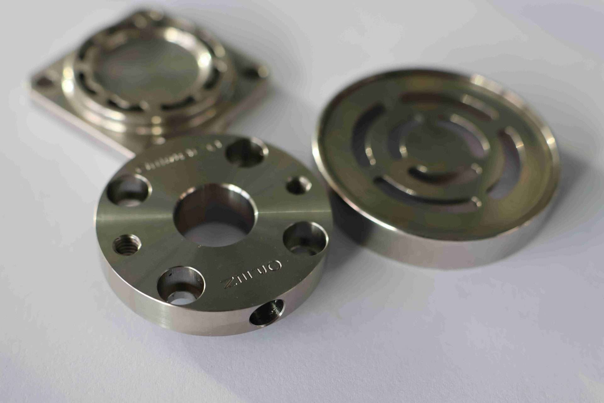

A hole may look like one of the simplest features on a CNC machined part.
In reality, holes can create some of the most important manufacturing decisions in a precision component.
A drawing may specify a simple diameter such as Ø10 mm. But that does not tell the manufacturer everything.
The engineering team may also need to consider:
- Hole diameter tolerance
- Hole position
- True position
- Roundness
- Cylindricity
- Hole depth
- Blind or through hole
- Surface roughness
- Mating component
- Thread requirements
- Material
- Production volume
- Inspection method
A general-purpose drilled hole may be perfectly adequate for one application.
Another application may require drilling followed by reaming.
A larger or particularly accurate bore may require CNC boring.
Choosing the correct process is therefore not simply a matter of making the hole to the nominal diameter.
The real question is:
What level of hole accuracy does the application actually require?
This distinction is important because unnecessarily specifying an extremely tight hole can increase machining time, tooling requirements and inspection cost. At the same time, using a basic drilling operation for a precision fit can result in assembly problems, excessive clearance, leakage, vibration or premature wear.
This guide explains how engineers can evaluate hole requirements and decide when drilling is sufficient and when additional operations such as reaming or boring are appropriate.
1. Why Hole Requirements Need More Than a Diameter
Consider a drawing that specifies:
Ø10 mm
A machinist still needs to know how much variation is acceptable.
For example, these requirements are very different:
Ø10 ±0.10 mm
and
Ø10 ±0.01 mm
The first allows a total tolerance range of 0.20 mm.
The second allows only 0.02 mm.
The manufacturing strategy may therefore be completely different.
The second requirement may require more controlled tooling, a more rigid setup, additional inspection or a finishing operation.
Hole requirements should also consider the function of the feature.
A clearance hole for a standard bolt does not necessarily require the same accuracy as a hole used for:
- Bearing installation
- Precision dowel location
- Hydraulic sealing
- Shaft guidance
- Bushings
- Alignment pins
- Rotating components
The function should determine the tolerance rather than automatically applying the tightest possible tolerance.
2. Drilling Is Usually the Starting Point
For most machined holes, drilling is the initial cutting operation.
A CNC machine positions the drill at the programmed coordinate and produces the hole according to the specified diameter and depth.
Modern CNC drilling can provide highly repeatable hole production when the tooling, workholding, cutting parameters and machine condition are properly controlled.
Drilling is particularly suitable for:
- Standard clearance holes
- Through holes
- General mounting holes
- Fastener holes
- Moderate-tolerance holes
- High-volume hole patterns
It is also one of the fastest ways to create material removal in a production environment.
However, drilling has inherent limitations.
A drill is not the same as a precision finishing tool.
Factors such as drill runout, tool wear, material behavior, chip evacuation, machine rigidity and workholding can affect the final hole.
For this reason, engineers should not assume that the nominal drill diameter automatically equals the final functional diameter.
3. When Is Drilling Enough?
Drilling is often sufficient when the hole is primarily used for clearance, fastening or general positioning and does not require a precision fit.
Typical examples include:
- Bolt clearance holes
- Mounting holes
- Access holes
- General fixture holes
- Drain holes
- Non-critical through holes
If the mating components do not require a controlled fit, additional finishing operations may provide little functional benefit.
For example, spending additional machining time to achieve an extremely smooth bore on a simple mounting hole may increase cost without improving the finished product.
This is an important Design for Manufacturability principle:
Specify precision where function requires it.
Do not automatically apply a precision-hole requirement to every hole on the drawing.
4. Hole Diameter Tolerance Is Only One Part of Accuracy
A hole can have the correct diameter and still cause an assembly problem.
Why?
Because the location may be incorrect.
Imagine a plate with four mounting holes.
Each hole may individually meet its diameter requirement.
But if one hole is shifted by 0.15 mm, the mating component may not fit.
This is where geometric tolerancing becomes important.
Engineers may need to control:
- Position
- Perpendicularity
- Concentricity
- Cylindricity
- Runout
For functional holes, the drawing should communicate not only how large the hole must be, but also where the hole must be and how accurately its geometry must be controlled.
5. Hole Position Can Be More Important Than Hole Diameter
Consider a dowel pin hole.
The pin may fit perfectly inside the hole.
But if the hole is in the wrong location, the assembly still fails.
This is why precision hole manufacturing often involves two separate questions:
Question 1
Can the required hole size be achieved?
Question 2
Can the hole be placed accurately relative to the required datum structure?
A high-quality hole therefore depends on both dimensional accuracy and positional accuracy.
The second requirement may influence:
- Fixture design
- Datum selection
- Number of setups
- Machine capability
- Tool selection
- Inspection method
For multi-face components, reducing the number of setups can also reduce positional variation.
6. What Does Reaming Do?
Reaming is a finishing operation used to improve an existing drilled hole.
Instead of removing a large amount of material like a drill, a reamer removes a relatively small amount of material and improves the final hole geometry and size.
A typical sequence may be:
Spot drill → Drill → Ream → Inspect
The drill creates the majority of the hole.
The reamer then finishes the hole to a more controlled dimension and surface condition.
This makes reaming useful for applications such as:
- Precision pins
- Bushings
- Bearing-related features
- Precision alignment holes
- Controlled clearance fits
The important principle is:
A reamer is generally not intended to replace the drilling operation.
The drilled hole needs to leave an appropriate amount of material for the reaming operation.
If too much material remains, the reamer may experience excessive cutting load.
If too little material remains, the reamer may not properly correct the hole.
7. When Should You Consider Reaming?
Reaming becomes attractive when a drilled hole is close to the required geometry but the application requires better dimensional consistency or surface quality.
For example, consider a hole intended to receive a precision cylindrical pin.
A general drilled hole may not provide the required fit.
The manufacturing route could therefore be:
Drill → Ream → Inspect
The correct reaming allowance depends on:
- Hole diameter
- Material
- Reamer type
- Cutting conditions
- Required tolerance
- Machine condition
Reaming should therefore be treated as part of a complete process rather than simply adding a reamer to the tool list.
8. Reaming and Surface Finish
Hole quality is not only about diameter.
Surface roughness can also influence:
- Sliding behavior
- Friction
- Sealing
- Bearing performance
- Press fits
- Lubrication
- Wear
A drilled hole may have a surface condition that is perfectly acceptable for a standard fastener.
But a precision sliding interface may require a smoother and more consistent bore.
Reaming can improve the internal surface compared with a basic drilled condition.
However, if an application requires a specific surface roughness value, that value should be stated clearly on the drawing.
A vague requirement such as “smooth hole” is difficult to quote and inspect consistently.
MFG SOLUTION’s CNC surface-finish guidance likewise emphasizes specifying an actual roughness requirement rather than relying on subjective descriptions.
9. What Is CNC Boring?
Boring is different from drilling and reaming.
A boring operation enlarges and refines an existing hole using a cutting tool that removes material from the internal diameter.
It can be used to improve:
- Diameter accuracy
- Hole alignment
- Concentricity
- Cylindricity
- Bore geometry
Boring is particularly useful for larger holes or applications where the relationship between the bore and other machined features is critical.
The process may begin with a drilled or cast opening.
The boring operation then brings the hole closer to its final specification.
MFG SOLUTION’s CNC boring resource describes boring as a process used to refine existing holes for improved geometric and dimensional accuracy.
10. Drilling vs Reaming vs Boring
A simplified comparison is useful:
| Process | Primary purpose | Typical application |
|---|---|---|
| Drilling | Create the initial hole | General holes, clearance holes |
| Reaming | Finish an existing hole | Precision fits and controlled diameters |
| Boring | Enlarge/refine an existing hole | Larger or highly controlled bores |
These processes are not necessarily competing alternatives.
They can be used together.
For example:
Drill → Bore → Ream
may be appropriate for a demanding application.
The correct sequence depends on the final geometry and tolerance requirements.
11. When Should Boring Be Preferred?
Boring is particularly useful when the hole itself is a major functional feature.
Examples include:
- Bearing bores
- Cylinder bores
- Large shaft bores
- Precision housings
- Alignment bores
- Large diameter mating features
Boring can also be useful when the hole needs to be related accurately to another machined surface.
For example, a housing may require a bore to be accurately positioned relative to a mounting face.
In this case, the machining sequence and datum strategy are important.
12. Deep Holes Create Additional Challenges
Hole depth can significantly change the manufacturing process.
A shallow hole is relatively easy to machine.
A deep hole introduces additional challenges:
- Tool deflection
- Chip evacuation
- Heat
- Vibration
- Drill breakage
- Hole wandering
- Coolant delivery
As the depth-to-diameter ratio increases, standard drilling methods may become less reliable.
The machining strategy may need to include:
- Peck drilling
- Specialized drills
- Internal coolant
- Multiple operations
- Pilot holes
- Boring
- Specialized deep-hole drilling
MFG SOLUTION’s CNC drilling guidance specifically highlights chip evacuation, coolant delivery and tool selection as critical factors for deep holes.
13. Blind Holes Need More Attention
A blind hole does not pass completely through the component.
This creates several additional considerations.
The drawing should ideally define:
- Hole diameter
- Required depth
- Thread depth if applicable
- Bottom condition
- Chamfer
- Tolerance
- Surface finish
The actual drill point also occupies part of the hole depth.
Therefore, engineers should distinguish between:
Overall drilled depth
and
Required usable cylindrical depth
This becomes particularly important for:
- Threaded holes
- Dowel holes
- Pin locations
- Hydraulic passages
- Precision inserts
If a mating component must enter a blind hole to a specific depth, the drawing should make the functional requirement clear.
14. Hole-to-Edge Distance Matters
A hole located too close to an edge can create manufacturing and structural problems.
From a manufacturing perspective, insufficient edge distance may cause:
- Workpiece deformation
- Burr formation
- Poor clamping
- Breakout
- Tool deflection
From a structural perspective, it may weaken the component.
The design should therefore consider the relationship between:
- Hole diameter
- Hole depth
- Wall thickness
- Edge distance
- Material
- Clamping method
A hole that looks acceptable in CAD may become difficult to manufacture if the surrounding material cannot adequately support the cutting force.
15. Hole Intersections Need Special Attention
Cross holes and intersecting bores can be more difficult than isolated holes.
For example:
A horizontal hole may intersect a vertical bore.
The intersection can create:
- Burrs
- Interrupted cutting
- Tool deflection
- Chip evacuation problems
- Difficult deburring
The manufacturing process should account for the intersection before production begins.
Deburring is particularly important in intersecting-hole designs because burrs can remain inside the passage.
MFG SOLUTION’s deburring guidance identifies cross-hole accessibility and edge condition as important design considerations.
16. Material Changes the Hole-Machining Strategy
Different materials respond differently to drilling and finishing.
Aluminum
Aluminum is generally highly machinable, but certain alloys can produce long chips or built-up material if tooling and cutting parameters are inappropriate.
Stainless Steel
Stainless steel can work harden and may require controlled cutting parameters and proper chip evacuation.
Titanium
Titanium has relatively low thermal conductivity and can generate challenging cutting conditions.
Brass
Free-machining brass grades can produce excellent chip formation and high productivity.
Engineering Plastics
Materials such as POM, nylon and PEEK can introduce thermal expansion, deflection and dimensional stability concerns.
The same hole tolerance may therefore require different machining strategies depending on material.
17. Tool Runout Can Affect Hole Accuracy
Tool runout is particularly important when machining small precision holes.
If a drill is not rotating concentrically, the cutting load becomes uneven.
Potential consequences include:
- Oversized holes
- Poor roundness
- Increased tool wear
- Poor surface finish
- Drill breakage
For precision applications, the condition of the:
- Toolholder
- Spindle
- Drill
- Collet
- Machine
should be considered.
MFG SOLUTION’s recent small-hole machining guidance specifically identifies toolholder runout as a major source of dimensional problems in small-diameter precision holes.
18. Workholding Can Affect Hole Position
A precision drill cannot compensate for a poorly positioned workpiece.
If the part moves during machining, the hole location can shift.
Workholding therefore needs to provide:
- Stable support
- Repeatable positioning
- Adequate clamping
- Minimal deformation
- Clear tool access
Thin-wall components require particular attention because excessive clamping force can deform the part.
After the part is released, the material may spring back and cause the measured hole position or geometry to change.
This is why hole accuracy is not purely a tooling issue.
It is a complete process issue.
19. Fewer Setups Can Improve Hole Position Accuracy
Suppose a component has holes on three faces.
One approach may require three separate setups.
Each setup introduces another positioning reference.
If the machine and geometry allow several features to be produced in one setup, positional consistency may improve.
This is one reason 5-axis machining can be valuable for complex parts.
A 5-axis machining center can potentially access multiple surfaces without repeatedly removing and repositioning the part.
However, 5-axis machining is not automatically required for every multi-face hole pattern.
The appropriate choice depends on:
- Geometry
- Tolerance
- Quantity
- Tool access
- Fixture design
- Cost
20. Hole Tolerance Should Match the Mating Component
One of the best ways to determine hole tolerance is to start with the mating component.
Ask:
What goes inside this hole?
Possible answers include:
- Standard bolt
- Dowel pin
- Shaft
- Bearing
- Bushing
- Threaded insert
- O-ring
- Hydraulic fitting
Each application creates different requirements.
For example, a clearance hole for a bolt usually needs enough clearance for assembly.
A dowel location may require a much more controlled fit.
A bearing housing may require a controlled bore size and geometry.
The hole tolerance should therefore be driven by the assembly requirement rather than chosen arbitrarily.
21. Do Not Over-Specify Every Hole
One of the most common cost problems in precision machining is unnecessary tolerance.
Imagine a component with 30 holes.
If all 30 holes are specified to an extremely tight tolerance even though only two holes are functionally critical, the manufacturer may need to apply additional process controls to all 30 features.
That can increase:
- Machining time
- Tooling cost
- Inspection time
- Rework risk
- Production cost
A better drawing distinguishes between:
Critical functional holes
and
General-purpose holes
This is a practical DFM principle.
MFG SOLUTION’s recent cost guidance similarly recommends applying tight tolerances only where the function requires them.
22. Hole Inspection Methods
The inspection method should match the requirement.
Depending on the application, manufacturers may use:
- Pin gauges
- Go/no-go gauges
- Bore gauges
- Micrometers
- CMM
- Optical measurement
- Plug gauges
- Coordinate measurement
For simple production holes, a go/no-go gauge may provide a fast and repeatable check.
For a complex bore requiring position and geometric verification, CMM inspection may be more appropriate.
Inspection should be considered during process planning rather than added after machining.
23. How Production Volume Changes Hole Processing
Quantity can influence the most economical hole-making process.
For prototypes:
Drill → inspect
may be sufficient.
For medium production:
Drill → ream → inspect
may provide a better balance for precision holes.
For high-volume components:
The manufacturer may evaluate:
- Specialized drills
- Automated tool changes
- Dedicated fixtures
- Reaming
- Boring
- Automated gauging
- Process monitoring
The objective is to achieve the required hole quality consistently while controlling cycle time.
24. A Practical Decision Tree
When reviewing a hole requirement, ask these questions in order.
Step 1: What is the hole used for?
General fastening?
Alignment?
Bearing?
Sealing?
Shaft support?
Step 2: What diameter tolerance is actually required?
Do not automatically use the tightest possible tolerance.
Step 3: Is position critical?
If yes, define the appropriate datum and geometric tolerance.
Step 4: Is surface finish important?
If yes, specify the required Ra value.
Step 5: How deep is the hole?
Check the depth-to-diameter ratio.
Step 6: Is the hole blind?
If yes, define usable depth and bottom requirements.
Step 7: What material is being machined?
Material affects tool selection and cutting strategy.
Step 8: What quantity is required?
Production volume can influence the optimal process.
Step 9: What inspection is needed?
Choose a measurement method that can actually verify the requirement.
25. Example: Three Different Ø10 mm Holes
Consider three components that all contain a nominal Ø10 mm hole.
Part A — General Mounting Hole
Purpose:
Bolt clearance.
Recommended approach:
CNC drilling
No additional precision finishing may be necessary.
Part B — Precision Pin Hole
Purpose:
Location with a dowel pin.
Recommended approach:
Drill → Ream → Inspect
The tighter fit justifies the additional finishing operation.
Part C — Precision Housing Bore
Purpose:
Bearing or shaft support.
Recommended approach:
Drill → Bore → Finish operation if required → Inspect
The bore geometry and relationship to other features may be more important than simply achieving a nominal diameter.
Same nominal diameter.
Three different manufacturing strategies.
That is why the function of the hole matters more than the number printed next to it.
26. What to Include on a CNC Drawing
For critical holes, consider specifying:
- Nominal diameter
- Diameter tolerance
- Hole depth
- Through/blind condition
- Position tolerance
- Datum references
- Surface roughness
- Chamfer
- Counterbore
- Countersink
- Thread specification
- Material
- Heat treatment
- Surface treatment
- Inspection requirements
The clearer the drawing, the easier it is for the manufacturer to select the correct process and provide an accurate quotation.
27. Questions to Ask Your CNC Supplier
If a hole is functionally important, ask the manufacturer:
- Is standard drilling sufficient?
- Would reaming provide better consistency?
- Is boring necessary?
- What machining sequence do you recommend?
- How will hole position be controlled?
- How will the hole be inspected?
- Is the specified tolerance necessary?
- Does the material create any drilling challenges?
- Is the hole too deep for standard tooling?
- Can the feature be completed in one setup?
- Will deburring affect the edge requirement?
- Does the surface finish requirement require a secondary operation?
These questions can reveal process risks before production starts.
28. How to Reduce Cost Without Sacrificing Hole Quality
The goal is not to make every hole as accurate as technically possible.
The goal is to make every hole accurate enough for its function.
Practical cost-reduction strategies include:
- Use standard drill diameters where possible.
- Avoid unnecessary tight tolerances.
- Use standard reamers.
- Avoid unnecessarily deep holes.
- Specify surface finish only where required.
- Reduce the number of setups.
- Design for tool access.
- Provide clear datum references.
- Avoid unnecessary blind holes.
- Group similar hole features where practical.
- Define inspection requirements clearly.
Good hole design can reduce both machining and inspection costs.
29. CNC Hole-Machining Checklist
Before releasing a drawing, check:
Geometry
- Hole diameter defined
- Hole depth defined
- Through or blind hole identified
- Counterbore/countersink specified
- Hole intersections reviewed
Tolerance
- Diameter tolerance defined
- Position tolerance defined where required
- Datums identified
- Surface finish specified where necessary
Manufacturing
- Material identified
- Tool access confirmed
- Depth-to-diameter ratio reviewed
- Workholding considered
- Number of setups reviewed
Quality
- Inspection method identified
- Critical dimensions identified
- Gauge requirements defined
- Inspection documentation defined
Commercial
- Quantity provided
- Annual demand provided
- Required delivery defined
- Secondary operations listed
FAQ
1. Is CNC drilling enough for precision holes?
It depends on the required tolerance, geometry, material and application. General-purpose holes can often be drilled directly, while precision fits may require reaming or boring.
2. What is the difference between drilling and reaming?
Drilling creates the initial hole and removes most of the material. Reaming is a finishing operation that removes a smaller amount of material to improve hole size and surface condition.
3. When should I use CNC boring?
Boring is useful when an existing hole needs improved diameter, alignment or geometric accuracy, particularly for larger or functionally important bores.
4. Does a tighter hole tolerance always mean better quality?
No. A tolerance should match the function of the component. An unnecessarily tight tolerance can increase manufacturing and inspection cost without improving performance.
5. Why can a drilled hole be larger than the drill diameter?
Drill runout, tool wear, material behavior, machine condition and cutting parameters can all affect the final hole size.
6. Should I specify surface roughness inside a hole?
If the internal surface affects sealing, friction, bearing performance, sliding, wear or assembly, a specific surface roughness requirement should be provided.
7. Are blind holes more difficult to machine?
They can be. Chip evacuation, usable depth, drill point geometry and tool access become more important than with simple through holes.
8. Can a CNC machine produce precision holes in one setup?
In many cases, yes. A suitable machine, fixture and tooling strategy can allow multiple hole features to be produced in one setup. Complex multi-face geometry may benefit from 5-axis machining.
Conclusion
Hole machining is often more complicated than simply drilling to a nominal diameter.
The correct process depends on the function of the hole and the level of accuracy actually required.
For general mounting and clearance holes, CNC drilling may be the most economical solution.
For precision fits, reaming can provide better dimensional consistency and surface quality.
For larger or highly controlled bores, CNC boring may be more appropriate.
The most important principle is:
Do not choose the machining process before understanding the functional requirement.
Start with the mating component.
Then define:
Function → Diameter → Tolerance → Position → Depth → Surface Finish → Material → Quantity → Inspection
This approach helps engineers avoid both extremes:
- Under-specifying a critical hole
- Over-specifying a non-critical hole
For CNC manufacturers and procurement teams, that distinction can have a direct impact on quality, lead time and cost.
If you have a part with precision holes, bores, threads or complex multi-face features, the engineering team can review the drawing and recommend an appropriate machining sequence before production begins.
Ready to Review Your CNC Hole Requirements?
Provide:
- 3D CAD file
- 2D drawing
- Material
- Quantity
- Hole tolerance
- Surface finish
- Mating component information
- Inspection requirements
A complete engineering review can help determine whether the part should use standard drilling, reaming, boring, 5-axis machining or a combination of processes.
Request an Engineering Review and Quotation
Contact the MFG SOLUTION Engineering Team
Related Manufacturing Topics
- CNC Machining
- CNC Hole Drilling
- CNC Boring
- CNC Turning
- 5-Axis CNC Machining
- CNC Machining Tolerances
- CNC Machining Surface Finish
- CNC Workholding
- CNC Deburring
- Quality Control
- Material Standards
- ISO Tolerances