
2026-05-31
Casting Shaft: Complete Guide to Manufacturing & Uses

| Key Insight | Explanation |
|---|---|
| What a casting shaft is | A casting shaft is a rotational or structural component produced by pouring molten metal into a mold, then finished through precision machining to meet tight dimensional tolerances. |
| Common materials used | Stainless steel, gray iron, ductile iron, aluminum alloys, and bronze are the most widely used materials for cast shaft production. |
| Casting vs. machining trade-offs | Casting creates the near-net shape cost-effectively at volume; CNC machining then refines critical surfaces to tolerances tighter than ±0.01mm. |
| Industries served | Automotive, medical devices, electronics, and industrial equipment all rely heavily on cast shafts for rotating and load-bearing assemblies. |
| Quality standards | ISO 9001:2015, IATF 16949, and ISO 13485:2016 are the primary quality frameworks governing casting shaft production for automotive, medical, and general manufacturing. |
| Post-casting finishing | Heat treatment, CNC turning, grinding, and surface finishing are standard post-casting operations that bring a shaft to its final specification. |
A casting shaft is a critical mechanical component produced through metal casting and subsequent precision machining. It serves as a load-bearing, torque-transmitting element in motors, pumps, gearboxes, and countless other assemblies. Understanding how casting shafts are made, finished, and qualified is essential for any engineer or procurement manager sourcing these parts at volume.
The global market for cast and machined shaft components continues to expand in 2026, driven by growth in electric vehicle drivetrains, medical robotics, and precision industrial equipment. Getting the manufacturing process right the first time isn’t optional; it directly affects product reliability, assembly yield, and total cost of ownership.
This guide covers everything you need to know: the definition and context of a casting shaft, the step-by-step production process, material selection, quality standards, common pitfalls, and expert best practices. Whether you’re evaluating suppliers or specifying a part for the first time, you’ll leave with a clear, actionable picture.
What Is a Casting Shaft?
A casting shaft is a rotational or structural component formed by pouring molten metal into a shaped mold cavity, then post-processed through machining to achieve final dimensional accuracy. The casting step creates the near-net shape; the machining step refines critical surfaces to tolerance. Together, these two operations produce a part that’s both geometrically complex and dimensionally precise.
Definition and Industrial Context
In manufacturing, a “shaft” refers to any elongated cylindrical component that transmits torque, supports rotating elements like bearings or gears, or acts as a structural axis within an assembly. A casting shaft specifically gets its base geometry from a casting process rather than from bar stock machining or forging alone.
According to industry data from Century Fasteners Corp., the investment casting process offers significant cost savings, design freedom, close tolerances, and shorter downstream machining time compared to machining from solid bar stock [1]. This makes casting an attractive starting point for complex shaft geometries that would require excessive material removal if machined from scratch.
- Rotational shafts: Transmit torque in motors, pumps, and gearboxes
- Structural shafts: Serve as fixed axes for rotating components like pulleys or rollers
- Hollow shafts: Reduce weight while maintaining torsional stiffness; a dedicated casting method exists for these, as documented in patent CN104226915B [2]
- Stepped shafts: Feature multiple diameters along their length to accommodate different mating components
Why the Casting-Then-Machine Approach Matters
Casting alone rarely achieves the surface finish or dimensional accuracy a shaft needs. Bearing seats, seal grooves, and threaded sections all demand tighter tolerances than casting can reliably deliver. That’s why a casting shaft is always a two-stage product: cast first, machine second.
AmTech OEM’s documented case studies illustrate this clearly. Their stainless steel shaft casting for a motor OEM features 316 SS construction with several tight-tolerance zones, achieved through precision machining after the initial casting step [3]. This hybrid approach lets manufacturers exploit casting’s geometric freedom while meeting the sub-0.05mm tolerances that assembled components require.
Pro Tip: When specifying a casting shaft, identify which surfaces are “critical” (bearing seats, seal diameters, keyways) versus “non-critical” (general body surfaces). Only critical surfaces need tight machining tolerances. Relaxing tolerances on non-critical surfaces cuts machining time and cost significantly.
How Casting Shaft Manufacturing Works
Casting shaft manufacturing follows a defined sequence from mold design through final inspection, with each stage directly affecting the quality and cost of the finished part.
Step-by-Step Production Process
- Design and mold engineering: Engineers create a 3D model of the shaft, accounting for shrinkage allowances (typically 1-2% for steel), draft angles, and parting line placement. The mold is then fabricated from sand, ceramic, or metal depending on the casting method chosen.
- Metal melting and pouring: The selected alloy is melted in an induction or arc furnace and poured into the prepared mold at a controlled temperature. Pouring temperature affects grain structure, porosity, and mechanical properties.
- Solidification and cooling: The metal solidifies in the mold. Cooling rate is managed to avoid internal stresses, hot tears, or shrinkage voids. Controlled cooling is especially critical for larger cross-sections.
- Shakeout and cleaning: The solidified casting is removed from the mold. Sand or ceramic shell is broken away. Gates, risers, and flash are cut or ground off.
- Heat treatment: Most cast shafts undergo annealing, normalizing, or quench-and-temper heat treatment to achieve target hardness and relieve residual stresses. This step is non-negotiable for automotive and medical applications.
- CNC machining: Critical surfaces are machined to final dimensions. CNC turning handles cylindrical features; CNC milling handles keyways, flats, and cross-holes. Swiss lathe machining excels for small-diameter shafts requiring concentricity within 0.005mm.
- Surface finishing: Grinding, honing, or polishing brings bearing and seal surfaces to the required Ra (surface roughness average) value, typically Ra 0.4-1.6 µm for shaft applications.
- Inspection and quality documentation: Dimensional inspection using CMM (coordinate measuring machine), hardness testing, and surface finish measurement confirm conformance to drawing. Full traceability documentation supports ISO and IATF audits.
Casting Methods Compared
| Casting Method | Typical Tolerance | Surface Finish (as-cast) | Best For | Typical Volume |
|---|---|---|---|---|
| Investment Casting | ±0.1–0.25mm | Ra 1.6–3.2 µm | Complex geometry, stainless, small-medium shafts | 100–100,000 pcs |
| Sand Casting | ±0.5–1.5mm | Ra 6.3–25 µm | Large shafts, iron, low tooling cost | 1–10,000 pcs |
| Die Casting | ±0.05–0.15mm | Ra 0.8–3.2 µm | Aluminum/zinc shafts, high volume | 10,000+ pcs |
| Centrifugal Casting | ±0.2–0.5mm | Ra 3.2–6.3 µm | Hollow shafts, cylindrical symmetry | 50–50,000 pcs |
McMaster-Carr’s catalog of cast shafts lists over 27,900 products across styles and sizes, which reflects just how broad the application range is for this component type [4]. Choosing the right casting method upfront determines how much downstream machining you’ll need, and that directly drives cost.
Key Benefits of Cast Shaft Production
Cast shaft production offers a compelling combination of geometric flexibility, material efficiency, and cost control that alternative manufacturing routes struggle to match at volume.
Design and Material Advantages
Casting allows engineers to incorporate features that would be prohibitively expensive to machine from bar stock. Internal cavities, integrated flanges, asymmetric cross-sections, and complex external profiles are all achievable through casting without adding machining operations.
- Near-net shape production: Less material removed during machining means lower raw material cost and faster cycle times
- Material flexibility: Investment casting works with stainless steel, carbon steel, aluminum, bronze, and specialty alloys that may not be available as standard bar stock
- Integrated features: Bosses, flanges, and mounting pads can be cast in, eliminating secondary welding or assembly operations
- Hollow shaft capability: Centrifugal and core-based casting methods produce hollow shafts that reduce weight without sacrificing torsional rigidity [2]
- Consistent grain structure: Properly controlled casting produces isotropic material properties across the cross-section, unlike some forging operations
Economic and Production Benefits
From a procurement standpoint, casting shafts offer predictable unit costs at volume. Tooling investment is front-loaded, but per-part costs drop substantially once production runs begin. Industry analysts suggest that for quantities above 500 pieces, investment casting typically delivers 30-50% lower total cost compared to machining from solid bar stock, depending on geometry complexity.
- Scalable production: The same mold serves thousands of parts with consistent dimensional repeatability
- Reduced machining time: Near-net shape means fewer passes on the CNC lathe, cutting cycle time and tooling wear
- Supply chain consolidation: A single casting-plus-machining supplier eliminates handoffs between vendors, reducing lead time and quality risk
- Certifiable quality: Casting processes governed by ISO 9001:2015 and IATF 16949 produce fully documented, auditable part histories
For procurement managers sourcing small precision shafts (up to 38mm diameter), partnering with a supplier that handles both casting and CNC machining in-house is particularly valuable. It eliminates the quality gap that often appears at the casting-to-machining handoff between separate vendors. For additional industry context on manufacturing process selection and supply chain topics, covers a range of relevant manufacturing and materials discussions.
Pro Tip: Request a Design for Manufacturability (DFM) review before finalizing your casting shaft drawing. A qualified machining partner can often suggest minor geometry changes that reduce casting scrap rates and machining cycle time by 15-25%, with zero impact on part function.
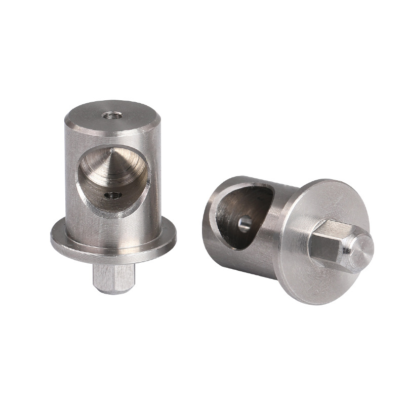
Common Challenges and Mistakes in Casting Shaft Production
Casting shaft manufacturing has well-documented failure modes. Most quality problems trace back to a handful of recurring mistakes in design, process control, or supplier selection.
Process and Design Pitfalls
A common mistake is under-specifying the casting drawing. Engineers sometimes provide only a finished-part drawing without a separate casting drawing that defines allowable as-cast dimensions, parting line locations, and draft angles. This forces the foundry to make assumptions, which introduces variability that machining can’t always correct.
- Insufficient draft angles: Draft angles below 1-2 degrees cause the casting to stick in the mold, leading to surface tears and dimensional distortion on the outer diameter
- Ignoring shrinkage allowance: Steel shrinks approximately 2% during solidification. Mold dimensions must compensate; failure to do so produces undersized castings that can’t be salvaged by machining
- Porosity in critical zones: Gas porosity (bubbles trapped during solidification) and shrinkage porosity (voids from uneven cooling) are the most common casting defects. Both weaken the shaft and create leak paths in hollow designs
- Residual stress cracking: Rapid or uneven cooling generates internal stresses. Without proper stress relief heat treatment, shafts can crack during machining or early in service life
- Mismatched machining allowance: Leaving too little stock for machining means surface defects from the casting can’t be cleaned up. The standard practice is 1.5-3mm of machining allowance on critical surfaces
Supplier and Quality Control Mistakes
One pitfall to watch for is selecting a foundry based on unit price alone, without verifying their process control documentation. A low-cost casting that requires 15% rework at incoming inspection is never actually cheap.
In practice, from experience working with automotive and medical device manufacturers, the most expensive quality failures occur when casting and machining are split between two suppliers who don’t communicate about process changes. A casting supplier who switches alloy heat or adjusts pouring temperature without notifying the machining shop can invalidate the downstream process parameters entirely.
- No incoming inspection protocol: Every casting batch should be dimensionally sampled and visually inspected before machining begins
- Missing material traceability: IATF 16949 and ISO 13485 require full material traceability from melt heat through finished part. Suppliers without this documentation create compliance risk
- Skipping non-destructive testing (NDT): For safety-critical shafts, magnetic particle inspection (MPI) or dye penetrant testing (DPI) should be specified to detect surface cracks not visible to the naked eye
- Overlooking concentricity requirements: A shaft that’s dimensionally correct at individual cross-sections but not concentric along its length will cause vibration and premature bearing failure in service
According to AmTech OEM’s documented production case, a cast shaft assembly measuring 6.71 inches long required plugs, dowels, and seals assembled after heat treating, highlighting how complex the post-casting process sequence can become when multiple features need precise coordination [5].
Best Practices for Casting Shaft Manufacturing in 2026
Effective casting shaft production in 2026 combines rigorous upfront engineering with disciplined process control and supplier qualification. The best manufacturers don’t just react to defects; they engineer them out before the first pour.
Engineering and Specification Best Practices
At MFG SOLUTION, we’ve found that the most successful casting shaft projects start with a complete design package: finished-part drawing, casting drawing, material specification (including heat treatment condition), and a critical characteristics list that identifies every dimension subject to functional verification.
- Define critical characteristics explicitly: Mark bearing seats, seal diameters, and keyway locations as “critical” on the drawing. This triggers enhanced inspection at every production stage
- Specify surface finish by function, not habit: Ra 0.8 µm on a bearing seat is justified. Ra 0.8 µm on a non-contact body surface wastes money. Match the finish spec to the functional requirement
- Use GD&T (Geometric Dimensioning and Tolerancing) correctly: Concentricity, runout, and cylindricity callouts are more meaningful than simple diameter tolerances for shaft applications
- Account for heat treatment distortion: Hardening operations move metal. Final grinding should be scheduled after heat treatment, not before
- Validate the first article formally: A First Article Inspection (FAI) per AS9102 or PPAP (Production Part Approval Process) per IATF 16949 confirms the process is capable before volume production begins
Supplier Selection and Quality Frameworks
As of 2026, the most reliable this method suppliers operate under at least one of three major quality frameworks: ISO 9001:2015 for general manufacturing, IATF 16949 for automotive supply chains, or ISO 13485:2016 for medical device components. These aren’t just certificates on a wall; they represent documented process control, calibrated measurement systems, and auditable corrective action processes.
- Verify certifications independently: Ask for the certificate number and confirm it’s current with the issuing body. Expired or fraudulent certifications are a real risk in offshore sourcing
- Evaluate machining capability, not just casting: A foundry that subcontracts CNC machining has less control over the finished shaft than a vertically integrated supplier
- Assess equipment depth: Swiss lathe capability is particularly valuable for small-diameter shafts (under 20mm) that require sub-0.01mm concentricity. Not every shop has this
- Require SPC data on critical dimensions: Statistical Process Control (SPC) data shows whether a process is in control, not just whether the last batch passed inspection
- Test with a small batch first: For new casting shaft programs, run 50-100 pieces before committing to full production volume. This surfaces process issues at minimal cost
Pro Tip: For small casting shafts under 38mm diameter, consider whether Swiss lathe machining of the critical features (rather than conventional CNC turning) is appropriate. Swiss lathes hold tighter concentricity on long, slender parts because the guide bushing supports the workpiece right at the cutting zone, eliminating deflection.
Sources & References
- Century Fasteners Corp., “Castings and Shafts,” 2026
- Google Patents, “CN104226915B – Casting Method of Hollow Shaft and Casting Mold,” 2026
- AmTech OEM, “Stainless Steel Shaft Casting,” 2026
- McMaster-Carr, “Cast Shafts,” 2026
- AmTech OEM, “Cast Shaft Assembly,” 2026
Frequently Asked Questions
1. What is a casting shaft used for?
A this strategy is used as a torque-transmitting or load-bearing component in motors, pumps, gearboxes, conveyors, and medical devices. The casting process produces the base geometry cost-effectively, while subsequent CNC machining delivers the precision surfaces needed for bearings, seals, and mating components. Applications span automotive drivetrains, industrial equipment, and medical robotics.
2. What materials are most commonly used for cast shafts?
Stainless steel (particularly 316 SS for corrosion resistance), gray iron, ductile iron, carbon steel, aluminum alloys, and bronze are the most common this approach materials. Material selection depends on the required mechanical properties, corrosion environment, weight constraints, and whether the shaft must meet food-grade, medical, or automotive standards.
3. How tight are the tolerances achievable on a casting shaft?
As-cast tolerances typically range from ±0.1mm (investment casting) to ±1.5mm (sand casting). After CNC machining of critical surfaces, tolerances of ±0.01mm or tighter are achievable. Swiss lathe machining is particularly effective for small-diameter the practices, holding concentricity within 0.005mm on diameters under 20mm.
4. What is the difference between a cast shaft and a forged shaft?
A cast shaft is produced by pouring molten metal into a mold, allowing complex geometries but producing an isotropic grain structure. A forged shaft is shaped by compressive force on solid metal, which aligns the grain structure along the part’s axis and typically produces higher fatigue strength. Forged shafts generally outperform cast shafts in high-cycle fatigue applications, but cast shafts offer greater geometric design freedom and lower tooling costs for complex shapes.
5. How do I specify machining allowance for a casting shaft?
The standard machining allowance for this practice critical surfaces is 1.5 to 3mm per side, depending on the casting method and part size. Investment castings need less allowance (1.5mm) due to their better as-cast accuracy. Sand castings require more (2.5-3mm) to ensure all surface defects are removed. Always specify machining allowance on the casting drawing, not the finished-part drawing.
6. What quality certifications should a casting shaft supplier hold?
For general manufacturing, ISO 9001:2015 is the baseline. Automotive applications require IATF 16949. Medical device components need ISO 13485:2016. As of 2026, any credible this method supplier serving regulated industries should hold at least one of these certifications and be able to provide a current certificate number for independent verification.
7. How long does it take to produce a casting shaft from drawing to delivery?
Lead time depends heavily on whether tooling already exists. New tooling for investment casting typically takes 3-6 weeks. Once tooling is proven, production lead times range from 2-4 weeks for standard orders. For small precision this strategys under 38mm diameter with existing tooling, suppliers with Swiss lathe and CNC turning capability in-house can compress finished-part delivery to under one week for urgent orders.
8. Can a casting shaft be produced from stainless steel?
Yes. Stainless steel this approachs are common in medical, food processing, and marine applications where corrosion resistance is critical. Grade 316 SS is the most frequently specified stainless alloy for the practice applications due to its excellent corrosion resistance and compatibility with investment casting. Post-casting, stainless shafts are typically passivated to restore the protective oxide layer after machining.
Conclusion
The this practice remains one of manufacturing’s most versatile component types, combining the geometric freedom of casting with the dimensional precision of CNC machining. Getting it right requires careful upfront design, the correct casting method for your geometry and volume, disciplined post-casting heat treatment, and a machining partner with proven capability on critical surfaces.
Results vary by application, material, and volume, so there’s no single formula that works for every this method program. What doesn’t vary is the importance of working with a supplier who controls the full process from casting through final inspection, holds the right quality certifications, and communicates clearly when process parameters change.
Our team at MFG SOLUTION recommends starting any new this strategy program with a thorough DFM review and a small first-article batch before committing to volume production. With ISO 9001:2015, ISO 13485:2016, and IATF 16949 certifications, 60+ engineering professionals, and Swiss lathe capability for shafts up to 38mm diameter, MFG SOLUTION is equipped to support your this approach program from specification through delivery, with quotes in 8 hours and shipment within 3 days.
About the Author
Written by the Manufacturing – Precision Machining & CNC Services experts at MFG SOLUTION. Our team brings years of hands-on experience helping businesses with Manufacturing – Precision Machining & CNC Services, delivering practical guidance grounded in real-world results.
Recommended Articles
Explore more from our content library: